) - pipe 2
only in the absence of the chamber
Chamber (see
section 2.4
Connecting the
chamber) pipe 1
and 2
2.
3
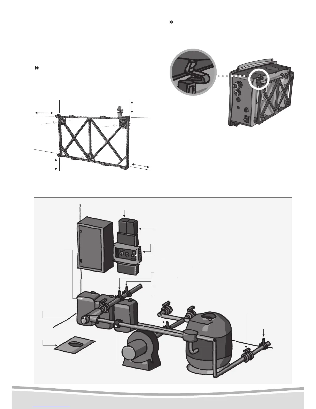
- Hydraulic connection
to a traditional ltration system
See above diagram.
Disposal of wastewater
Regarding the disposal of reagents, please refer
to the technical regulations drawn up by your
local sewage department.
Check that the clip is
properly positioned
ENGLISH
2.
2
- Mounting the box
Mount your device on the wall, preferably protec-
ted from bad weather, and close to the ltration
box in order to facilitate the electrical connections.
Avoid direct exposure to sunlight.
Mounting the wall support
Keep to the following sizes (in mm). They indicate
the obligatory minimum spacing between the sup-
port and other elements on the wall.
Note :attachment screws and plugs are provided.
Ensure that the holes are ø 8 mm in diameter.
liquid chlorine injection
(
)
- pipe 5
Chlorine reagent (“RCL” pipe)
pH reagent (“RpH” pipe)
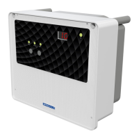
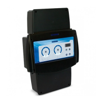
Switch
Digital display (controls
the device’s functions)
Evacuation
pipe 4
pH+ or pH- injection option
(
)
- pipe 1 and 8
Pressure-relief kit option (see p.10 - Pressure-relief kit option) )
Corrector
tanks: pH-,
pH+ and liquid
chlorine pipe
3,6 and 7
Gravity
evacuation
List of pipes
1. pH- injection
2. Water sampling
3. pH- suction
4. Drains
5. Liquid chlorine
injection
6. pH+ suction
7. Liquid chlorine suction
8. pH+ injection
Place the device on the support
Fit the bottom of the device into the grooves on
the wall support and clip the top into place.