18
2.
4
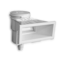
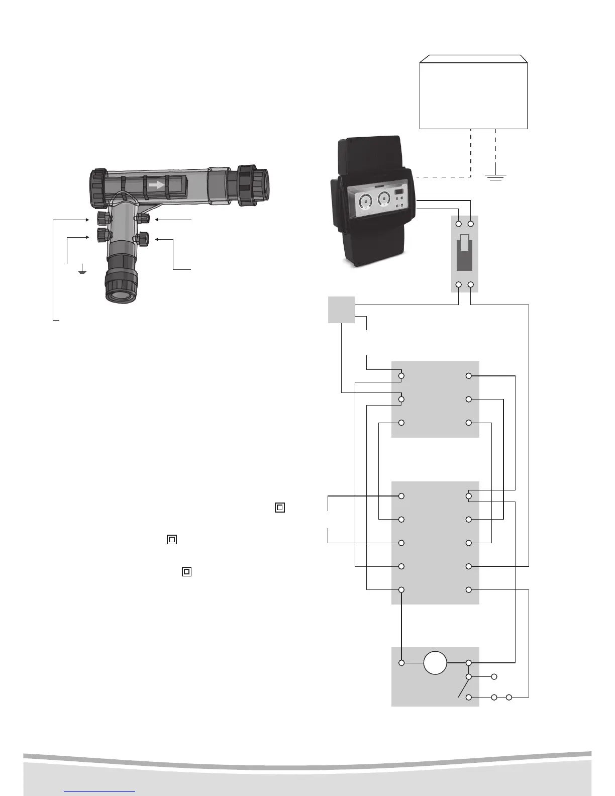
- Connecting the chamber
This operation only applies to models tted with
an electrolyser.
A more detailed installation guide is supplied
with the chamber.
Note: water ows in a single direction within the
chamber.
ENGLISH
Flow detector
Earth
pH- injection
(
)
pipe 2
The direction of ow is indicated by an arrow.
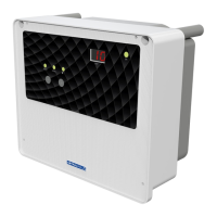
2.
5
- Electrical connections
The electrical connection must be carried
out by a qualied electrician in conformity
with the NFC I5-100 (Edition 2002) standard.
See diagram opposite.
If using electrolysers other than Energys, or a chlo-
rine meter pump :
-
check if it is a class II device: there should be a
symbol on the device.
-
if it is a class II device (
symbol, no earth): the
connection is identical to that for an Energys.
-
if it is a class I device (no symbol, presence
of earth wires): the equipotential bonding (earth
wire) must be connected directly between the
device’s box and the ltration box. The earth
cable must not pass via the Selwatch box.
4A-AM
Thermal-
magnetic
circuit
breaker
Single-phase
220V
220V
50/60 Hz
4A max
ELECTROLYSER (E)
OR EXTERNAL
CHLORINE PUMP
(PCL)*
SWITCH
2
2
1
1
4
4
14
3
3
13
6
6
A2
5
5
A1
CONTACTOR
N
Pump
CLOCK
.A
Manual
turn-on
M