Back
20
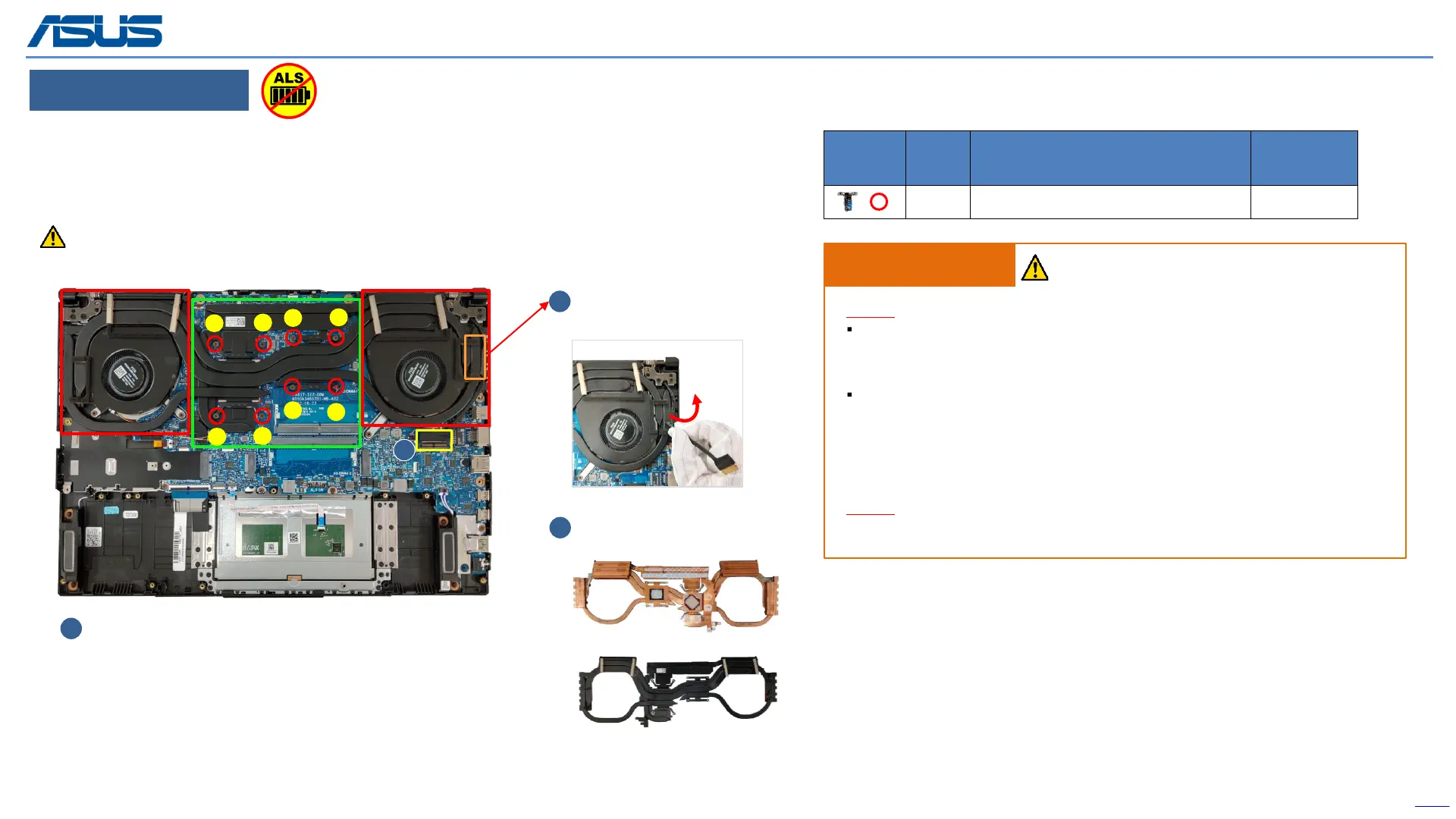
Disassembly Notice
Step 1 : Disconnect (yellow mark) EDP connector*1pc.
Step 2 : Release the EDP cable.
Step 3 : Follow the reverse screws numbers to remove screws*8pcs.
Step 4 : Remove THERMAL MODULE.
Remove (Red mark) Screws
3
THERMAL MODULE
Remove
4
2
Release EDP cable on
Thermal module
Screws QTY Spec
Torque
(kgf-cm)
8 M2*4L (5,0.8) (K) #1 2.0±0.2
Assembly Notice
Step-1
THERMAL MODULE Location:[VRAM/CHOKE/MOS]
Material: FCR-AS Grease
MB Location:[GPU/CPU]
Material:
Main (GA500 Grease)
Substitute (Thermal pad)
Step-2
Please follow the screws numbers to lock screws *8pcs.
Recommend that the force point is at green block, and pull up thermal module to take it out.
Do not pull up at red block and also notice the thermal pipe should not have deformation.
1
2
3
4
5
6
7
8
1
The device has an Ambient Light Sensor (ALS) for power-off protection Function.
IMPORTANT! Thermal paste, thermal pads, liquid metal, or other thermal
interface materials must be thoroughly removed and replaced if this
component is removed. Ensure that replacement materials are available
before proceeding, or contact an authorized service center for assistance.
WARNING! The heat sink contains liquid metal and should only be removed by
authorized service personnel. Significant damage may occur to motherboard
components if the heat sink is improperly removed.
 Loading...