8-3. Alarm Output (high- and low-limiter output)
The alarm output functions based on the established range of acceptable measurement values.
When a value is detected that falls outside of the acceptable range alarm output is transmitted from
the detection section.
The high-limiter and low-limiter output circuit has a photocoupler with a transistor open collector in
the final stage. See the diagram on the following page before using the limiter circuit.
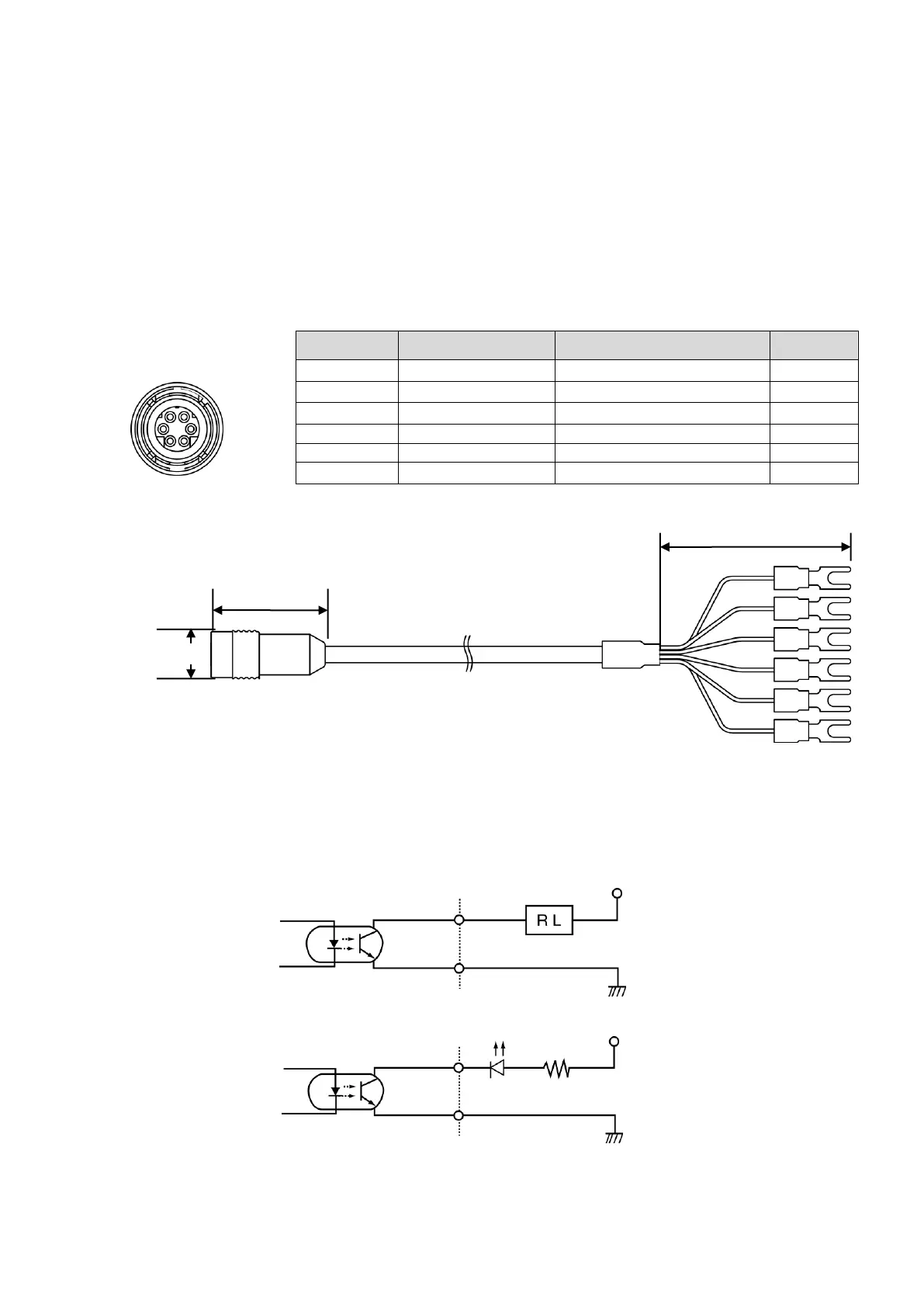
① Dedicated cable (option) specifications (Fig.8-6 and Fig.8-7)
Pin numbers 1 to 3 are used for the alarm output.
Pin numbers 4 to 6 are used for switching the scales. Refer to pg. 20, "8-4Switching the Scale
(externally)."
Table 8-3 Lead wire color
Fig.8-6
Fig.8-7
② High- and low-limiter output typical applications
The high-limiter and low-limiter output circuit has a photocoupler with a transistor open collector in
the final stage. Before using the limiter circuit, see Fig.8-8, Fig.8-9 and Fig.8-10.
a. Drive a relay
Fig.8-8
b. Turn on a LED
Fig.8-9
Wire number plug
front view