This section offers a very basic description of the protocol for communication between an Series 16
controller and a computer ( referred to below as “the host”). For a more complete description and details on
the communication protocols, please refer to Communications Manual.
Message strings may be of two types — commands to controller or responses from controller.
General Comments
One host and multiple controllers may be interconnected on a single bus. The host may send commands to
any controller and may receive responses from any controller. Each controller on the bus is assigned an
identification code between 00 and 99. No two controllers on a given bus may have the same identification
code. Controllers are not capable of communicating with other controllers.
Every valid message begins with a pound-sign (#) character.
Every valid message ends with a carriage-return (<CR>)
character.
A valid message is composed of: Start Message, Controller ID Code, Command, Parameter and Data.
Every response begins with a line-feed (<LF>) character and ends with a carriage-return, line-feed pair
(<CRLF>).
Digital
Communications
Caution: Modifying parameter #19 (Baud Rate) by host may cause loss of data link.
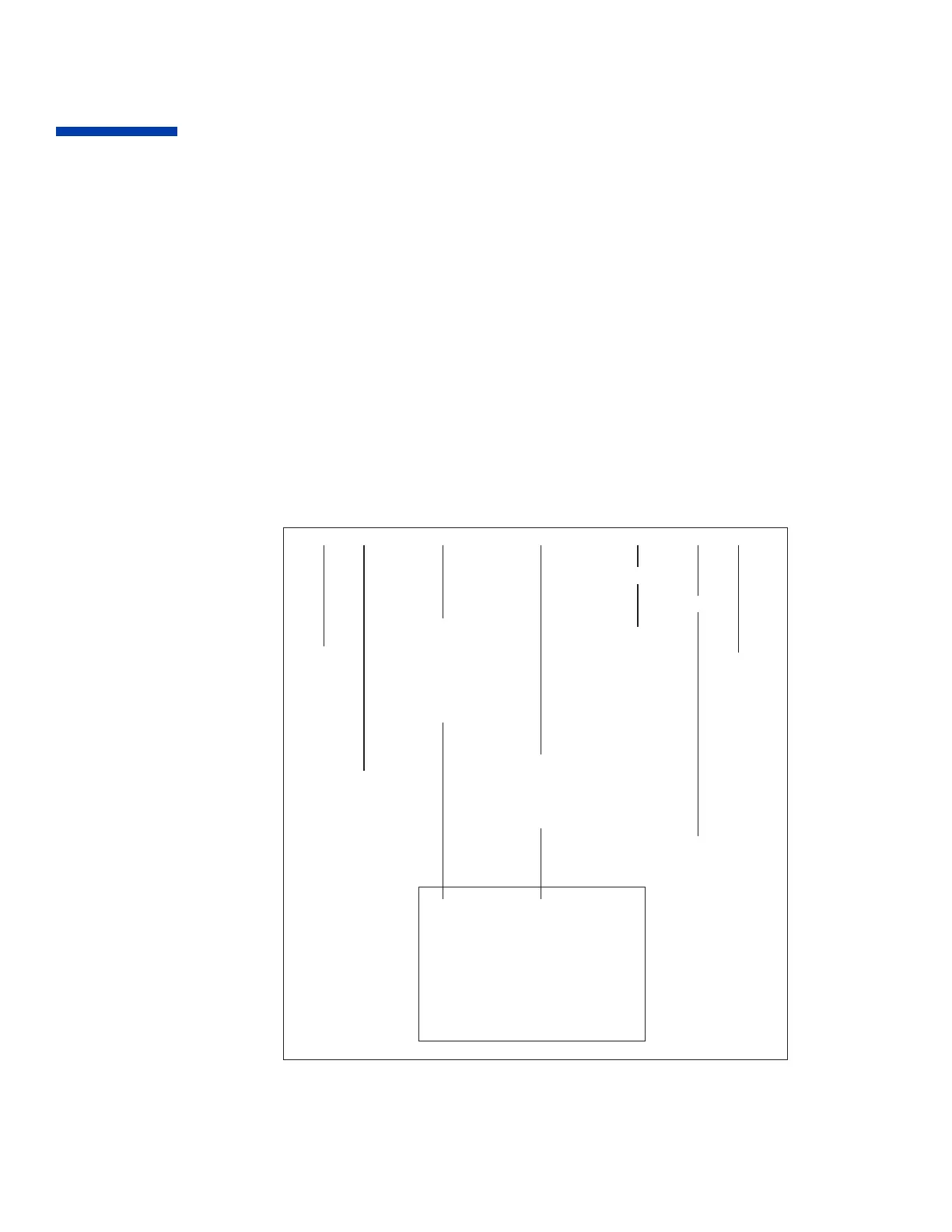
#[controller id] [command] [parameter number]<new value><units> [CR]
Start of
message
End of
message
Up to TWO
Numeric
Characters
00 to 99
Up to TWO
Numeric
Characters
00 to 99
Up to SIX
Characters
ONE Leading
Sign
‘-’,‘+’ or
Space and
FOUR
Numeric
Characters
with decimal
for decimal
parameters
OPTIONAL
OPTIONAL
ONE
Character
Upper case
or Lower
case
R Read
M Modify
E Enter
ONE
Character
F Deg F
C Deg C
U PROCESS
SENSOR
None for
default
Temperature
units or NON-
THERMAL
parameters
N ON
(Select)
F OFF
(Deselect)
? STATUS
0 Standby
1 Autotune
2 Manual
3 Ramp
9 Version
(Status Only)
SPECIAL
COMMANDS
For Standby “On”, type #01N0[CR].
Figure 18. General Communications Message Format
 Loading...