21 1800296 C
Description of the Generator
Controls and Indicators
Front Panel Connectors and Indicators
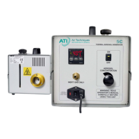
Figure 1 Front Panel Features
1. Main Power Input – Recessed 3-prong, IEC320-C13 power inlet
connector. Use only the power cord provided with the unit.
2. Fuse Holder – Houses the main power fuses and is located inside
the Main Power Input.
3. Power ON / OFF switch – Turns main power ON and OFF.
4. Function Keys – All temperature control parameters are factory
pre-set and do not require adjustment.
5. Temperature Display – Displays the temperature of the thermal
unit. The display indicates if the Main Power Switch is ON.
6. Aerosol ON/OFF Switch – Controls flow of liquid aerosol reagent
to the thermal unit once the generator is up to temperature. The
switch has a green LED light that illuminates when the switch is ON.
6. Aerosol Switch
7.
1. Main Power
Input
5. Temperature
Display
4. Function Keys
8. Inert Gas Inlet
2. Fuse Holder
3. Power ON/OFF
Switch