2920 1462 00
8
Instruction book
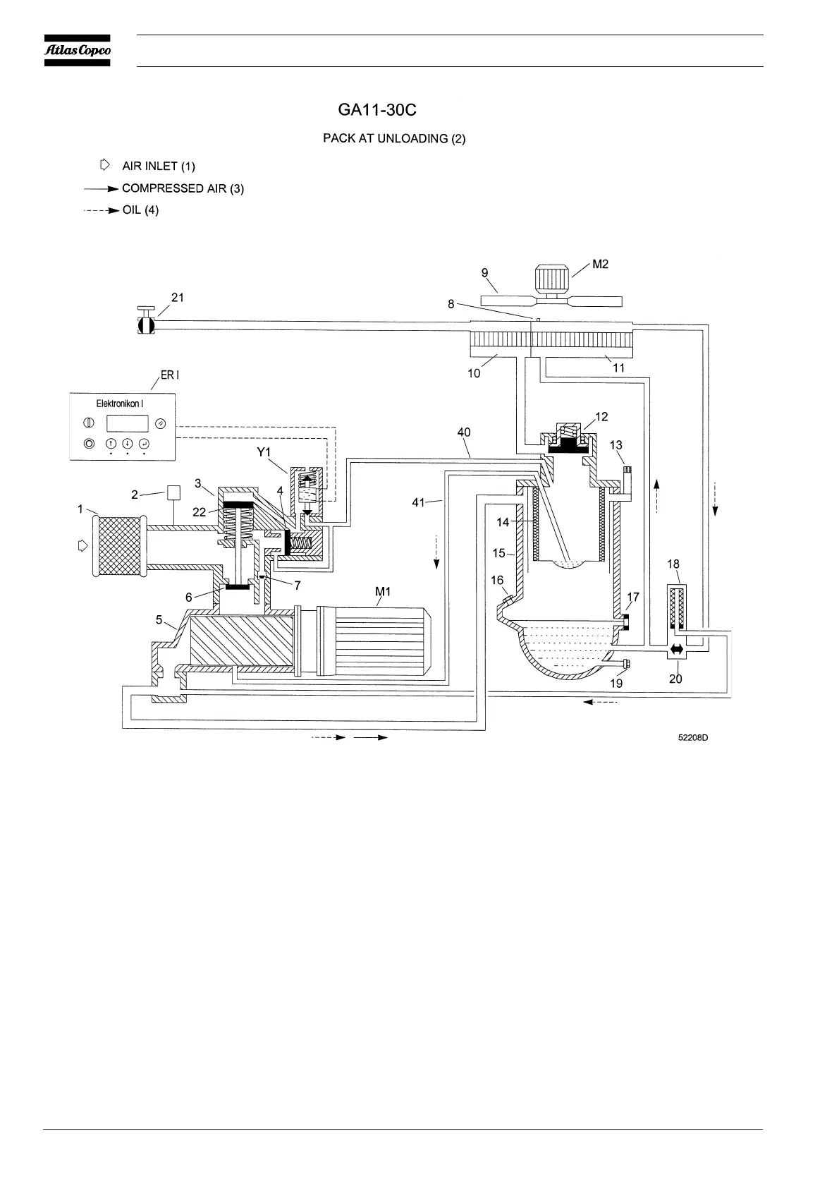
Fig. 1.8 GA Pack during unloading
ER I Elektronikon I regulator
ER II Elektronikon II regulator
M1 Drive motor
M2 Motor, compressor cooling fan
Y1 Loading solenoid valve
1 Air filter
2 Air filter service indicator
3 Unloader
4 Unloading valve
5 Compressor element
6 Inlet valve
7 By-pass valve
8 Vent plug, oil circuit
9 Compressor cooling fan
10 Air cooler
11 Oil cooler
12 Minimum pressure valve
13 Safety valve
14 Oil separator element
15 Air receiver
16 Oil filler plug
17 Oil level indicator
18 Oil filter
19 Oil drain plug
20 Oil cooler by-pass valve
21 Air outlet valve
22 Loading plunger
23 Manual condensate drain valve
24 Automatic condensate outlet
25 Condensate trap
40 Flexible, control air
41 Flexible, oil scavenging
On Full-feature also:
26 Pressure sensor
27 Capillary tube
28 Condenser cooling fan
29 Refrigerant condenser
30 Hot gas by-pass valve
31 Air/refrigerant heat exchanger/
evaporator
32 Liquid refrigerant dryer/filter
33 Air/air heat exchanger
34 Accumulator
35 Insulating block
36 Temperature sensor
37 Motor, condenser fan
38 Refrigerant compressor
39 Fan control switch
Figs. 1.7 and 1.8 Air-oil and unloading-loading systems
 Loading...


