Fieldbus
216 (428) 9836 3123 01
Hardware
Fieldbus connectors
The ProfiBus-DP standard EN 50170 (DIN 19245) recommends the use of a 9 pin female D-sub
connector. Depending on the protection class and type of application, other connector designs are also
allowed.
Connector 9-pin female D-sub
Positive RxD/TxD according to RS485 specification
Request to send
+5V BUS and GND BUS are used for bus termination. Some devices, such as optical transceivers
(RS485 to fiber optics) may require an external power supply from these pins.
Isolated GND from RS484 side
+5V BUS and GND BUS are used for bus termination. Some devices, like optical transceivers
(RS485 to fiber optics) may require an external power supply from these pins.
Isolated +5V from RS484 side
+5V BUS and GND BUS are used for bus termination. Some devices, like optical transceivers
(RS485 to fiber optics) may require an external power supply from these pins.
Negative RxD/TxD according to RS485 specification
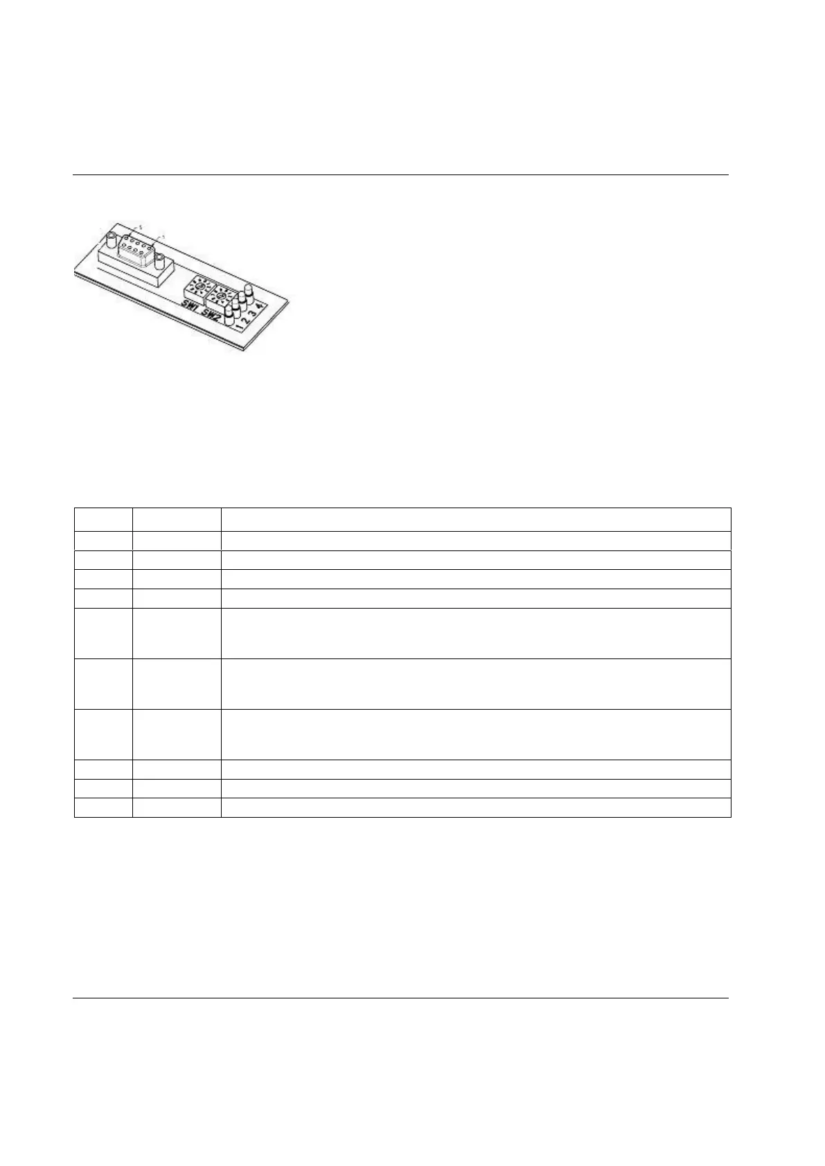
Node address
Node address is set with the two rotary switches on the fieldbus module; this enables address settings from
1-99 in decimal form.
Switch 1 x10 / Switch 2 x1. (See switches on the top drawing)
Example: Address = (Left Switch Setting x 10) + (Right Switch Setting x 1)
 Loading...