- 18 -
2.3.3 Safety devices
The engine electronics monitor the engines
parameters and generate warning and shut-down
signals when the parameters reach a preset treshold
value.
2.3.4 Bodywork
The alternator, the engine, the cooling system, etc. are
enclosed in a sound-insulated bodywork that can be
opened by means of side doors (and service plates).
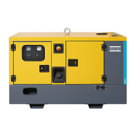
The generator can be lifted by using the lifting eye
integrated in the bodywork (roof). To be able to lift
the QAS 500 by means of a forklift, rectangular holes
are provided in the frame.
The earthing rod, connected to the generator’s earth
terminal is located at the bottom of the frame on the
outside.
2.3.5 Control panel
The control panel grouping volt and amp meters,
control switch etc., is placed at the rear end.
2.3.6 Data plate and serial number
The generator is furnished with a data plate showing
the product code, the unit number and the power
output (see “Dataplate” on page 104).
The serial number is located on the right-hand front
side of the frame.
2.3.7 Drain plugs and filler caps
The drain holes for the engine oil, the coolant and the
plug for the fuel, are located and labelled on the frame
at the service side.
The drain flexibles for the engine oil and the engine
coolant can be brought to the outside of the generator
through the drain hole.
2.3.8 External fuel tank connection
The external fuel tank connection allows to bypass
the internal fuel tank and to connect an external fuel
tank to the unit.
Make sure to connect the fuel supply line as well as
the fuel return line. Connections to fuellines ought to
be air-tight to prevent air from entering the fuel
system.
2.3.9 Spillage free skid
A Spillage free skid with forklift slots allows the
customer to transport the generator easily with a
forklift. It avoids accidental spilling of engine fluids
and thus helps to protect the environment.
The leaking fluid can be removed via drain holes,
secured by drain plugs. Tighten the plugs firmly and
check for leakages. When removing the leaking fluid,
observe all relevant local legislation.
The drain hole can also be used to
guide external fueltank connections.
When connecting an external
fueltank, use the 3-way valves.
Position 1: Indicates that the
fuel supply line to the engine is
connected to the internal
fueltank.
Position closed: Indicates that
the fuel supply line to the engine
is closed.
Position 2: Indicates that the
fuel supply line to the engine is
connected to the external
fueltank.
 Loading...

