- 60 -
Installation wirings
– The link between X25.10 & X25.11 has to be
removed.
– Mains breaker feedback lines have to be wired to
X25.10/X25.11/X25.12.
– Mains breaker control lines have to be wired to
X25.13/X25.14/X25.15/X25.16. These terminals
are voltage free contacts. The power for the MB
has to be supplied by the customer (24 Vdc/
230 Vac) (max. contact rating K11, K12 = 250 V/
16 A).
– The Mains sensing lines L1/L2/L3/N have to be
wired to terminals X25.3/X25.4/X25.5/X25.6.
– Make sure the connections between X25.33 &
X25.3; X25.34 & X25.4; X25.35 & X25.5;
X25.36 & X25.6 are removed.
– Power Transducer lines have to be wired to
X25.21 (input) and X25.22 (GND).
– Verify all settings for paralleling set up (see
“Paralleling”).
Transformer Maintenance (TM) operation
This application is normally used in combination with
SEMI-AUTO mode in installations with the Mains. It
is only applicable in combination with a Transformer
Maintenance Box.
The purpose of the transformer maintenance mode is
to enable repair of or service on a transformer by
disconnecting the Mains from the system.
The generator will start up and synchronise with the
busbar to connect to the electrical system. When the
generator is synchronised, the generator breaker will
close and the generator starts taking the load. When
the Mains power is zero, the mains breaker can be
switched off or the fuses can be removed.
After repair or service of the transformer the
generator will be backsynchronised to the mains and
fuses can be restored. Power is moved from generator
to mains again before disconnecting.
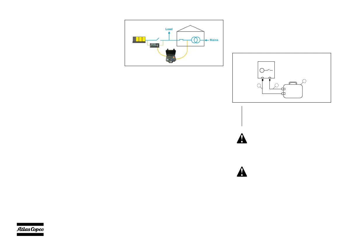
Installation wirings
– The link between X25.10 & X25.11 has to
beremoved.
– Plug the Transformer Maintenance Box cables
into Transformer Maintenance Box connectors
X40 and X41 on the cubicle.
1 Transformer Maintenance Box (1626 4629 00)
2 Control cable (25 m) (1626 4630 00)
3 Sensing cable (25 m) (1626 4631 00)
To protect the unit and the load, a
suitable protection installed on the
power cables between the Mains and
the generator should be foreseen by
the end-user.
For more information on
Transformer Maintenance, refer to
the Transformer Maintenance
manual.

 Loading...


