168
ATmega8535(L)
2502K–AVR–10/06
• Bit 5:4 – UPM1:0: Parity Mode
These bits enable and set type of parity generation and check. If enabled, the Transmit-
ter will automatically generate and send the parity of the transmitted data bits within
each frame. The Receiver will generate a parity value for the incoming data and com-
pare it to the UPM0 setting. If a mismatch is detected, the PE Flag in UCSRA will be set.
• Bit 3 – USBS: Stop Bit Select
This bit selects the number of stop bits to be inserted by the Transmitter. The Receiver
ignores this setting.
• Bit 2:1 – UCSZ1:0: Character Size
The UCSZ1:0 bits combined with the UCSZ2 bit in UCSRB sets the number of data bits
(character size) in a frame the Receiver and Transmitter use.
• Bit 0 – UCPOL: Clock Polarity
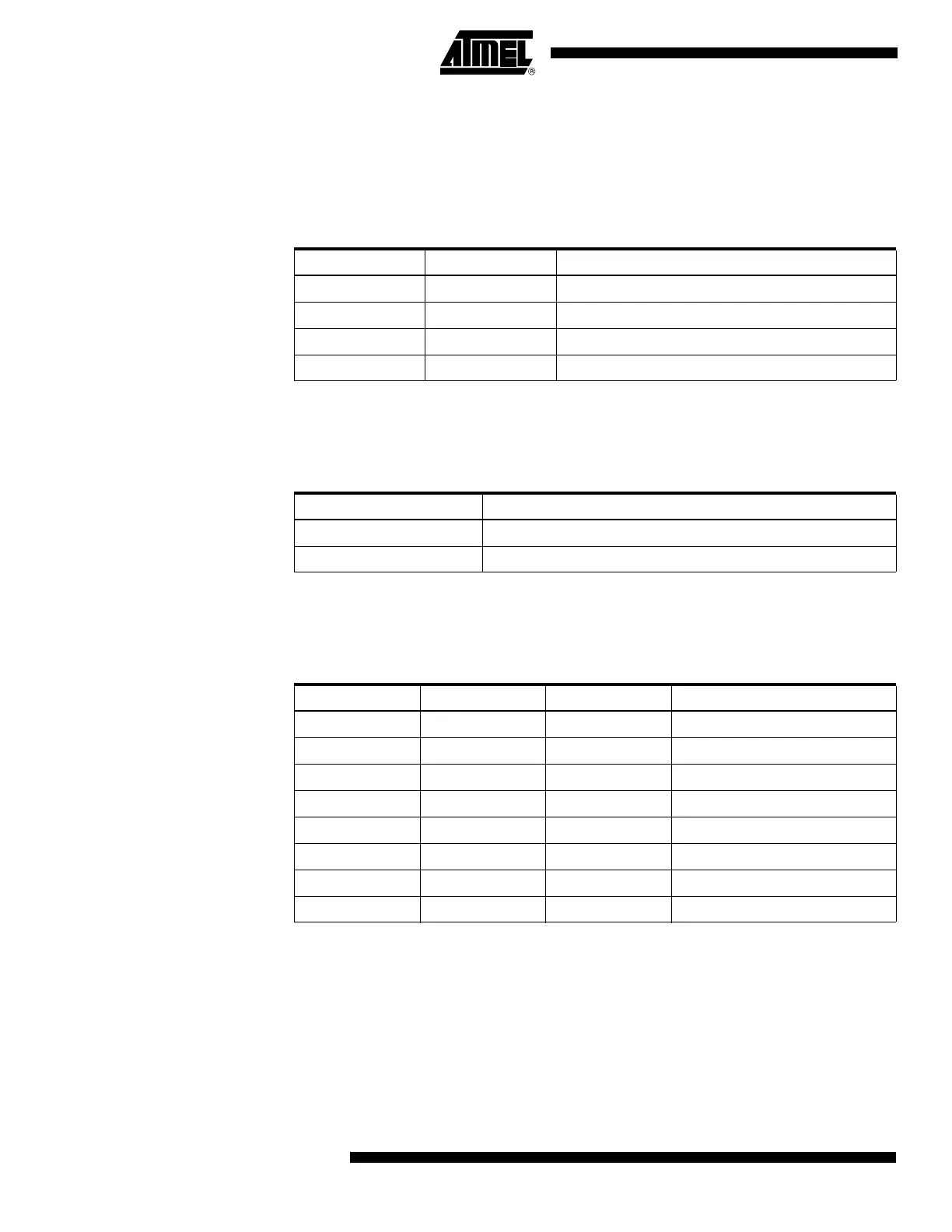
Table 65. UPM Bits Settings
UPM1 UPM0 Parity Mode
0 0 Disabled
01Reserved
1 0 Enabled, Even Parity
1 1 Enabled, Odd Parity
Table 66. USBS Bit Settings
USBS Stop Bit(s)
01-bit
12-bit
Table 67. UCSZ Bits Settings
UCSZ2 UCSZ1 UCSZ0 Character Size
0005-bit
0016-bit
0107-bit
0118-bit
100Reserved
101Reserved
110Reserved
1119-bit