37
ATmega8535(L)
2502K–AVR–10/06
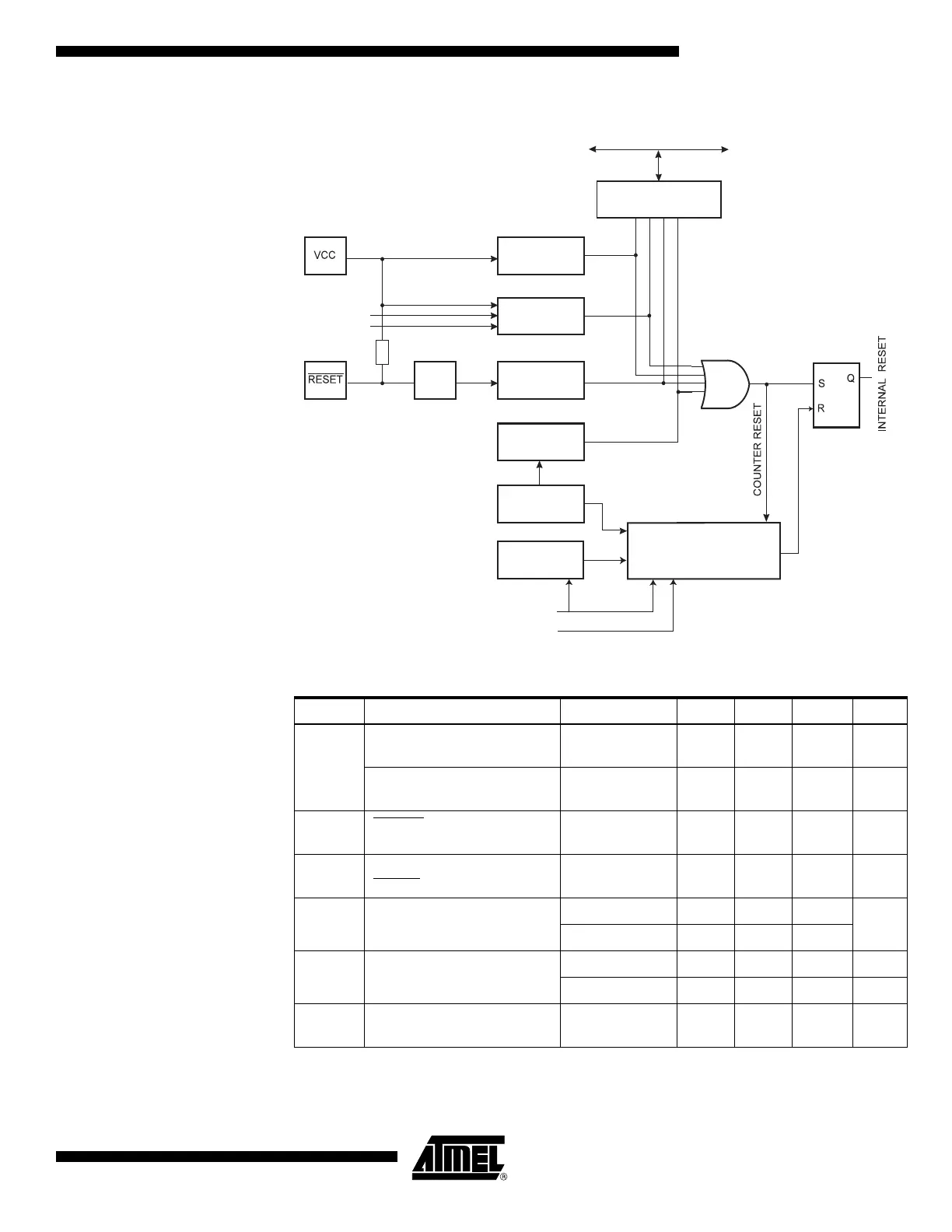
Figure 15. Reset Logic
Notes: 1. Values are guidelines only.
2. The Power-on Reset will not work unless the supply voltage has been below V
POT
(falling).
Table 15. Reset Characteristics
Symbol Parameter Condition Min
(1)
Typ
(1)
Max
(1)
Units
V
POT
Power-on Reset Threshold
Voltage (rising)
1.4 2.3 V
Power-on Reset Threshold
Voltage (falling)
(2)
1.3 2.3 V
V
RST
RESET Pin Threshold
Voltage
0.2 0.9 V
t
RST
Minimum pulse width on
RESET Pin
1.5 µs
V
BOT
Brown-out Reset Threshold
Voltage
(3)
BODLEVEL = 1 2.5 2.7 2.9
V
BODLEVEL = 0 3.6 4.0 4.2
t
BOD
Minimum low voltage period
for Brown-out Detection
BODLEVEL = 1 2 µs
BODLEVEL = 0 2 µs
V
HYST
Brown-out Detector
hysteresis
130 mV
MCU Control and Status
Register (MCUCSR)
Brown-out
Reset Circuit
BODEN
BODLEVEL
Delay Counters
CKSEL[3:0]
CK
TIMEOUT
WDRF
BORF
EXTRF
PORF
DATA BU S
Clock
Generator
Spike
Filter
Pull-up Resistor
Watchdog
Oscillator
SUT[1:0]
Power-on
Reset Circuit
Reset Circuit
Watchdog
Timer