305
7679H–CAN–08/08
AT90CAN32/64/128
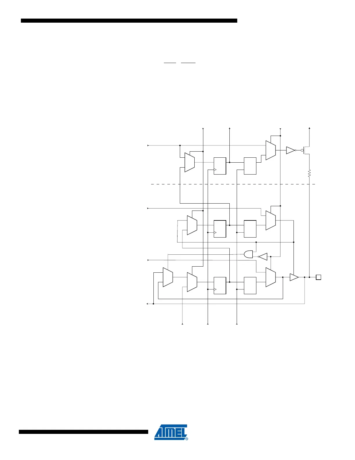
When no alternate port function is present, the Input Data – ID – corresponds to the PINxn Reg-
ister value (but ID has no synchronizer), Output Data corresponds to the PORT Register, Output
Control corresponds to the Data Direction – DD Register, and the Pull-up Enable – PUExn – cor-
responds to logic expression PUD
· DDxn · PORTxn.
Digital alternate port functions are connected outside the dotted box in Figure 23-4 to make the
scan chain read the actual pin value. For Analog function, there is a direct connection from the
external pin to the analog circuit, and a scan chain is inserted on the interface between the digi-
tal logic and the analog circuitry.
Figure 23-3. Boundary-scan Cell for Bi-directional Port Pin with Pull-up Function.
DQ DQ
G
0
1
0
1
DQ DQ
G
0
1
0
1
0
1
0
1
DQ DQ
G
0
1
Port Pin (PXn)
VccEXTESTTo Next CellShiftDR
Output Control (OC)
Pullup Enable (PUE)
Output Data (OD)
Input Data (ID)
From Last Cell
UpdateDRClockDR
FF2 LD2
FF1 LD1
LD0FF0

 Loading...


