42
8068C–AVR–06/08
XMEGA A3
25. DAC - 12-bit Digital to Analog Converter
25.1 Features
• One DAC with 12-bit resolution
• Up to 1 Msps conversion rate for each DAC
• Flexible conversion range
• Multiple trigger sources
• 1 continuous output or 2 Sample and Hold (S/H) outputs for each DAC
• Built-in offset and gain calibration
• High drive capabilities
• Low Power Mode
25.2 Overview
The XMEGA A3 devices features two 12-bit, 1 Msps DACs with built-in offset and gain calibra-
tion, see Figure 25-1 on page 42.
A DAC converts a digital value into an analog signal. The DAC may use an internal 1.1 voltage
as the upper limit for conversion, but it is also possible to use the supply voltage or any applied
voltage in-between. The external reference input is shared with the ADC reference input.
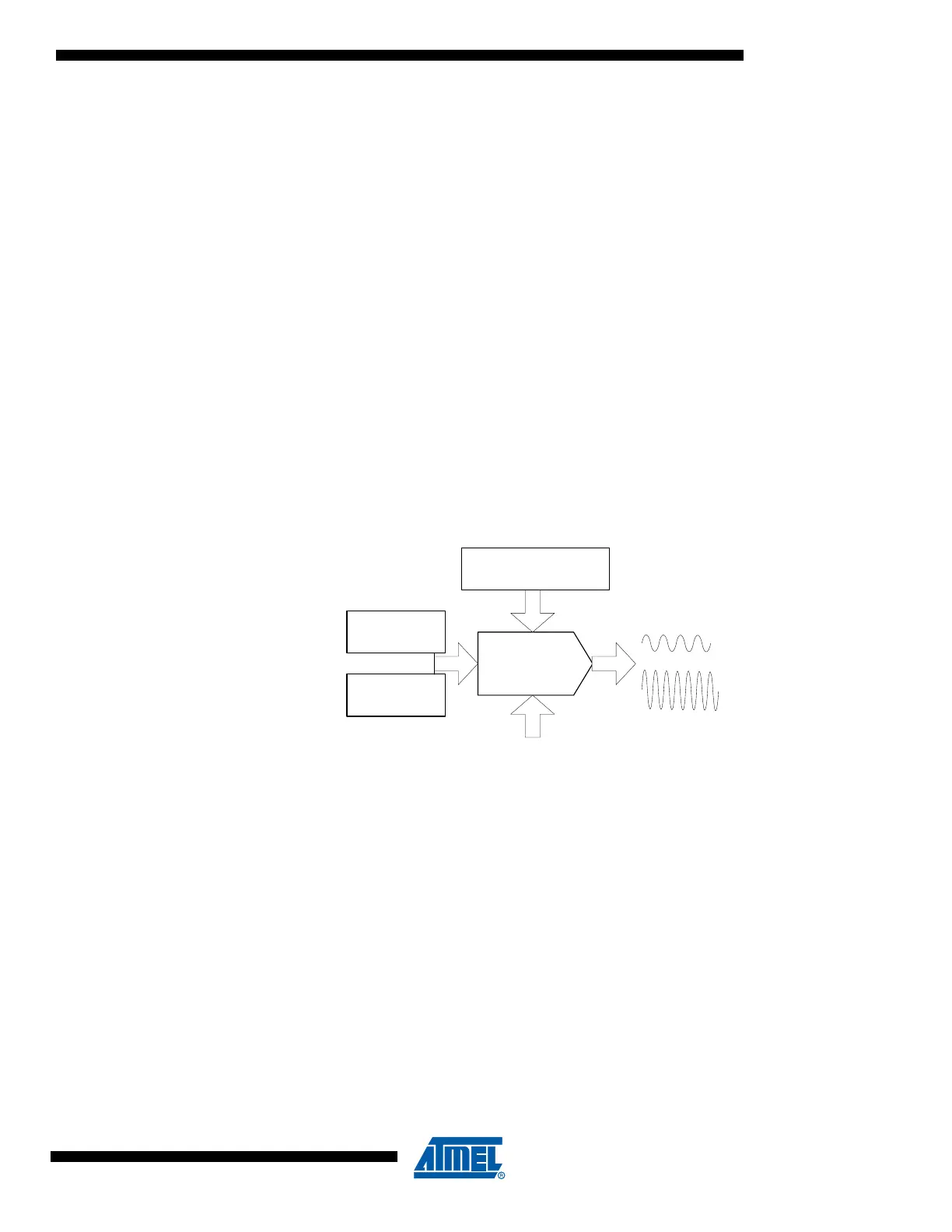
Figure 25-1. DAC overview
Each DAC has one continuous output with high drive capabilities for both resistive and capaci-
tive loads. It is also possible to split the continuous time channel into two Sample and Hold (S/H)
channels, each with separate data conversion registers.
A DAC conversion may be started from the application software by writing the data conversion
registers. The DAC can also be configured to do conversions triggered by the Event System to
have regular timing, independent of the application software. DMA may be used for transferring
data from memory locations to DAC data registers.
The DAC has a built-in calibration system to reduce offset and gain error when loading with a
calibration value from software.
PORTB each has one DAC. Notation of this peripheral is DACB.
DAC
Channel A
Register
Channel B
Register
Event
Trigger
Configuration
Reference selection
Channel A
Channel B

 Loading...


