© 2008 • All rights reserved. 7
DLA2/4/6 Speaker Level Audio Router
2. System Design Overview
There are four typical system applications when installing the DLA2/4/6:
Standard A/V or Stereo Receiver1.
Zone 2 Output of an A/V Receiver2.
External Ampli er3.
Sub-Zone of a Multi-Room Controller 4.
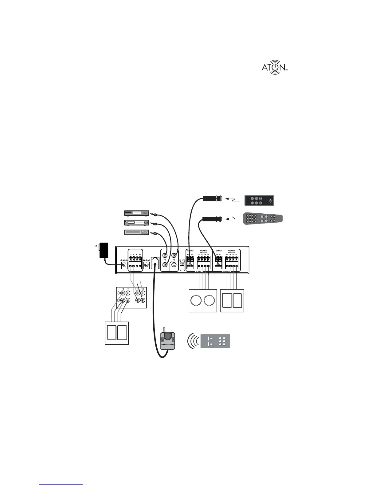
Figure 2-1 shows a DLA2 connected to an A/V receiver with optional ATON accessories includ-
ing optional AIR3 IR Receivers, AIE2 IR Emitters and a DLA2RKT RF remote Kit. This system
is capable of house-wide control of the DLA2 through the RF Kit as well as Room 1 and Room
2 control using the included IR Remote. A universal remote or source remote can be used to
control the DLA 2/4/6* as well as the equipment connected to the IR EMITTER OUTPUTS for
even more convenience.
CLASS 2 WIRING
IR EMITTER OUTPUTS
IMPEDANCE
MAT CH
RF
INPU T
PATE NT
PENDING
PWR IN
12VDC / 2.1A
SENSE
INPU T
9VDC / 100mA
8
8
4 4
AMPLIFIER
INPU T
1
PAGE/DB
TRIG IN
AIR3
IR Receivers
(Optional)
DLA2
A/V Receiver
A/V Receiver
Satellite
DVD
AIE2
IR Emitters
(Optional)
Room 1
Speakers
Room 2
Speakers
16/4
Speaker
Cables
16/4
Speaker
Cables
Included IR
Remote Control
(Controls DLA2/4/6)
+
-
L
L
R
R
OUT
Room 1
Room 2
OUT
Main
Speakers
RF
Receiver
(Optional)
Universal/Source
IR Remote Control
ROOM 1
ROOM 2
ALL
ON
ALL
OFF
SCENE
VOL
+
-
VOL
MUTE
DLA2RKT
RF Remote Kit
(Optional)
16/4
Speaker
Cables
Figure 2-1: System Overview
* DLA discrete IR codes available for download at: www.atonhome.com. See Appendix C-3.