AT
15
Hex wrench
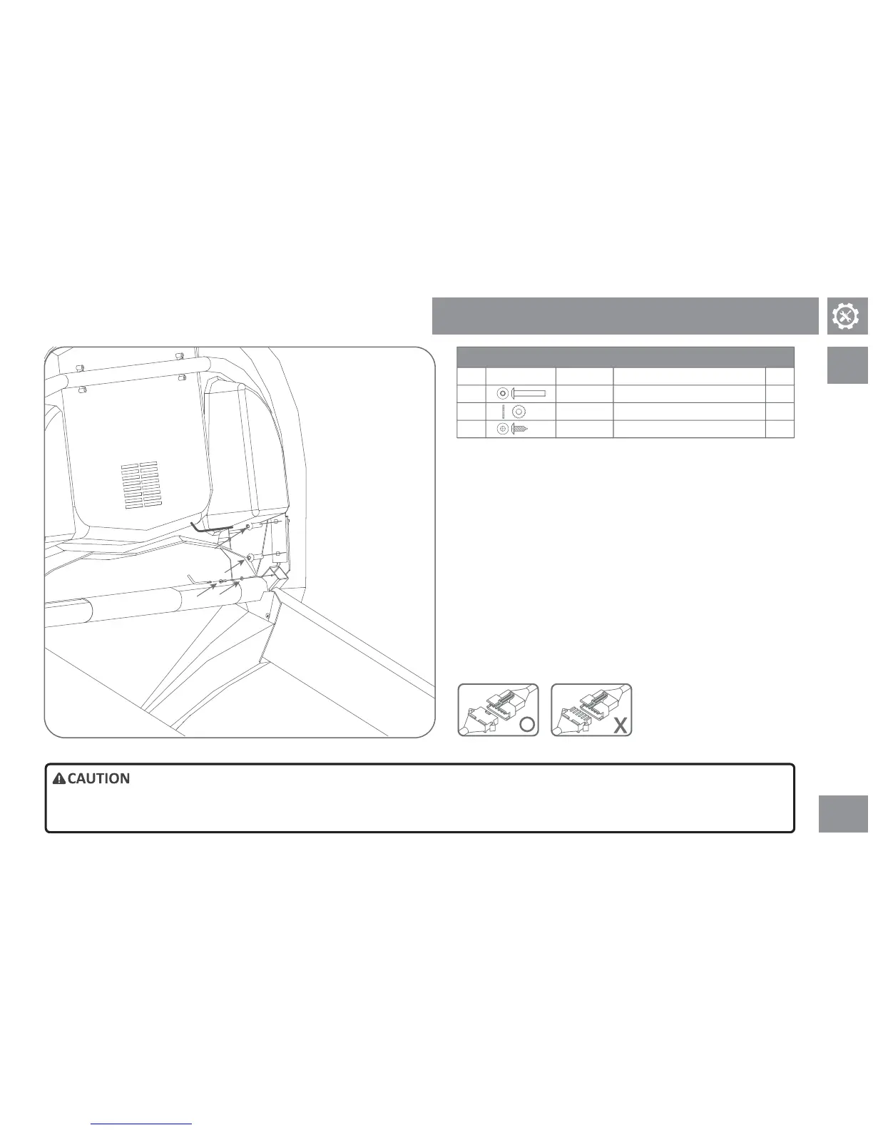
1) Get the instrumentaon unit.
2) Insert the screw through the le armrest retainer and the instrument unit
bracket carefully, make sure screws and washers are well posioned and
parally ghtened.
3) Repeat step 2 to secure the right instrumentaon unit bracket fixaon.
4) Remove instrument unit's le grounding wire, use the included combo
tool to secure component B, C, and grounding wire to the uncoated square
holes of the armrest square tube.
Note: Place component B in the inner side and direct contact with the square
tube as shown in figure on the le.
5) Connect the sensing wire at both sides of the front armrest to the le and
right hand of instrument unit.
6) Connect the console cable to the connecng cable on the console.
Hardware pack for step 5
QtyDescriponParts
A
B
C
TypeIllustraon
4
1
1
Screw
Screw
• Please assemble the display console with great care. Make sure no wire is pressed or bent to avoid any damage.
Step 5 of Assembly Procedure
Truss head Phillips screw (10L)
Toothed washer (Ø10)
Washer
Buon Head Socket Bolt (34L)
A
A
C
B
Phillips screwdriver