Version 6.0 17 March 2010
Installation Manual 2. Installing the Device
The 50-pin male Telco cable connector must be wired according to the pinouts in the table
below, and to mate with the female connector illustrated in the figure below.
Figure 2-8: 50-pin Female Telco Board-Mounted Connector
Table 2-3: E1/T1 Connector Pinouts for Each 50-pin Telco Connector
E1/T1 Trunk Number Tx Pins (Tip/Ring) Rx Pins (Tip/Ring)
1 to 8 9 to 16
1 9 27/2 26/1
2 10 29/4 28/3
3 11 31/6 30/5
4 12 33/8 32/7
5 13 35/10 34/9
6 14 37/12 36/11
7 15 39/14 38/13
8 16 41/16 40/15
¾ To connect E1/T1 trunks using RJ-48c connectors (1-, 2-, 4-, 8-trunk
device):
1. Connect the E1/T1 trunk cables to the ports labeled PSTN 1 to 8 (in the case of the 8-
trunk device) on the device's rear panel.
2. Connect the other ends of the Trunk cables to the PBX/PSTN switch.
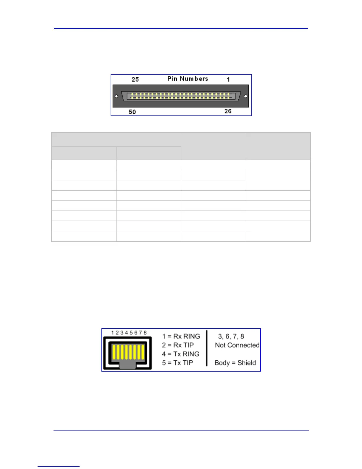
RJ-48c trunk connectors are wired according to the connector pinouts shown in the figure
below:
Figure 2-9: RJ-48c Connector Pinouts

 Loading...


