Version 6.0 41 March 2010
Installation Manual 4. Monitoring the Device
4 Monitoring the Device
The operating status of the device can be monitored in the following ways:
Monitoring the device's hardware front-panel LEDs (refer to 'Front-Panel LEDs' on
page 41).
Monitoring the device using the Web interface (refer to 'Web Interface' on page 42).
4.1 Front-Panel LEDs
The operating status LEDs on the front panel of the device are described in the tables
below:
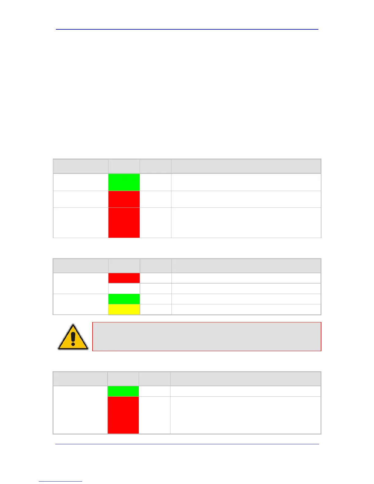
Table 4-1: Chassis LEDs Description
Location Color State Description
Right side of
front panel
Green On
The power is on.
Right side of
front panel
Red On
At least one of the internal fans has significantly
reduced its speed or has stopped (i.e., fan failure).
Left side of front
panel
Red On
One of the two AC redundant power supplies is faulty
or disconnected from the AC/mains outlet (i.e., power
supply failure). This LED is only relevant for the dual
AC power supply.
Table 4-2: Status LEDs Description
Label Color State Description
FAIL
Red On device failure (fatal error).
- Off Normal functioning.
ACT
Green On Initialization sequence terminated OK.
Yellow On N/A.
Note: During correct operation, the ACT LED is lit green and the FAIL LED is off.
Changing of the FAIL LED to red indicates a failure.
Table 4-3: E1/T1 Trunk Status LEDs Description
Label Color Status Description
T1/E1 Status
1 to 8
T1/E1 Status
9 to 16
Green On Trunk is synchronized (normal operation).
Red On
Loss due to any of the following signals:
LOS Loss of Signal
LOF (Loss of Frame)
AIS (Alarm Indication Signal -- 'Blue alarm')
RAI (Remote Alarm Indication -- 'Yellow alarm')

 Loading...


