Installation Manual 42 Document #: LTRT-70113
Mediant 2000
Note: On the front panel, 16 LEDs are provided for 16-span units and 8 LEDs are
provided for 1-span, 2-, 4-, and 8-span units. In the case of 1-, 2-, and 4-span
units, the extra LEDs are not used.
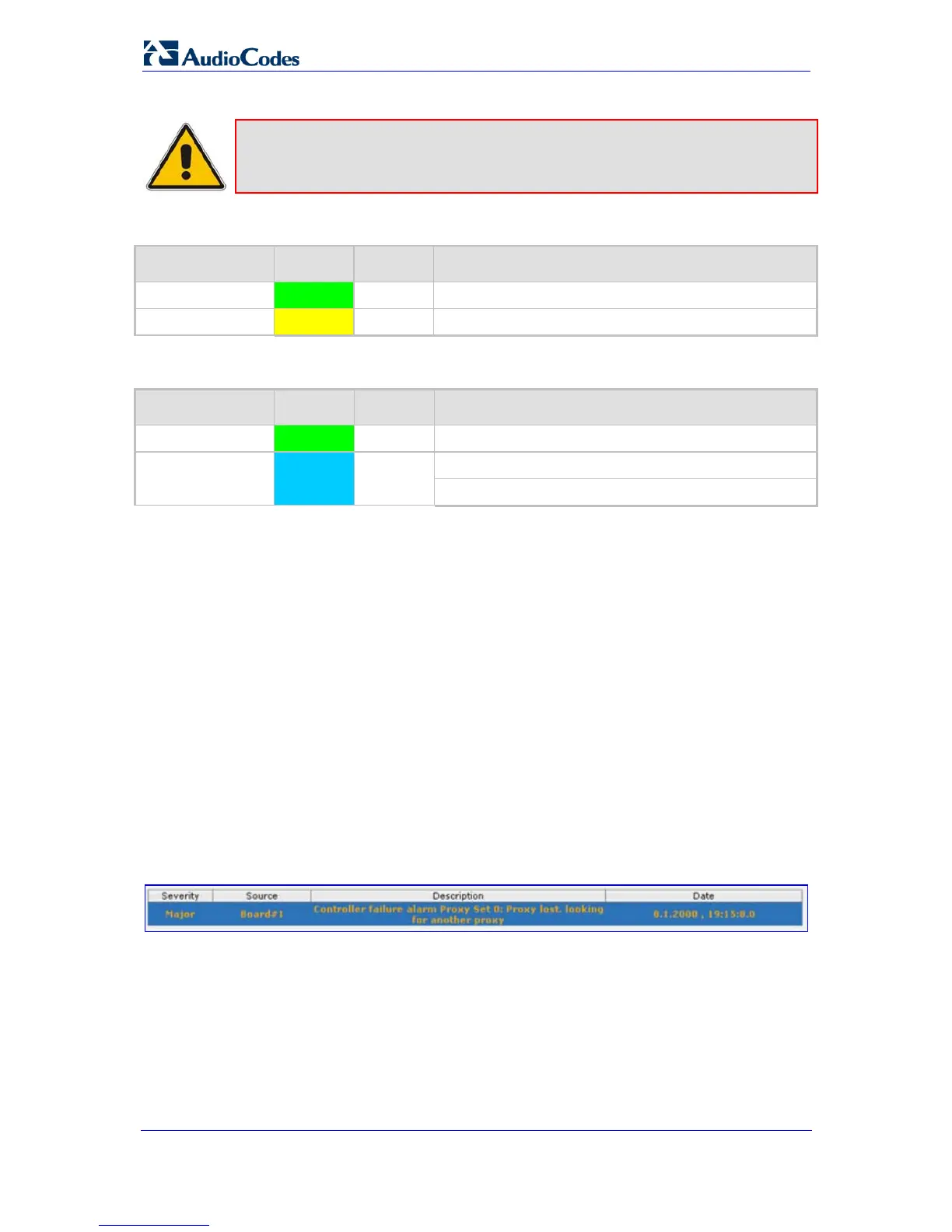
Table 4-4: Ethernet LEDs Description
Label Color Status Description
LINK
Green On Link all OK.
ACT
Yellow On Transmit / receive activity.
Table 4-5: Blade LEDs Description
Label Color Status Description
PWR
Green On Power is supplied to the blade.
SWAP READY
Blue On
The blade can be removed.
The blade was inserted successfully.
4.2 Web Interface
The Web interface's 'Home' page provides a graphical display of the device's front panel,
displaying color-coded icons depicting the status of the device's ports and channels, as well
as other interfaces of the device. In addition, the 'Home' page allows you quick access to
viewing active alarms.
4.2.1 Viewing Alarms
The 'Home' page allows you quick access to the 'Active Alarms' page (typically accessed
from the Status & Diagnostics tab > Status & Diagnostics menu > Active Alarms). This
page lists all the device's current alarms.
¾ To view a list of current alarms, take this step:
In the 'Home' page, click the area labeled Alarms; the 'Active Alarms' page appears:
Figure 4-1: Current Alarms in Active Alarms Page
For each listed alarm, the following information is displayed:
• Severity: severity level of the alarm:
♦ Critical (displayed in red)
♦ Major (displayed in orange)
♦ Minor (displayed in yellow)
♦ No alarm (displayed in green)

 Loading...


