List of Figures
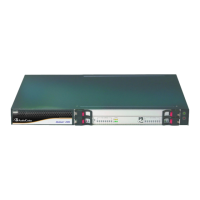
Figure 3-1: Mediant 800B Front Panel................................................................................................... 16
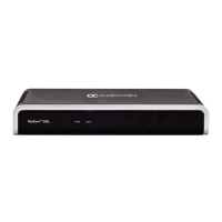
Figure 3-2: Mediant 800C Front Panel .................................................................................................. 16
Figure 3-3: Mediant 800B Rear Panel ................................................................................................... 22
Figure 3-4: Mediant 800C Rear Panel ................................................................................................... 22
Figure 4-1: Rubber Foot Attached to Underside of Device.................................................................... 25
Figure 4-2: Attaching the Mounting Brackets to Chassis ....................................................................... 26
Figure 4-3: Attaching the Chassis with Mounting Brackets to Wall ....................................................... 27
Figure 4-4: Mounting Brackets ............................................................................................................... 29
Figure 4-5: Attaching the Mounting Brackets ........................................................................................ 29
Figure 5-1: Grounding the Device .......................................................................................................... 32
Figure 5-2: LAN Port-Pair Groups and Web Interface String Names .................................................... 33
Figure 5-3: Connecting the LAN Ports ................................................................................................... 34
Figure 5-4: RJ-11 Connector Pinouts for FXS Interface ........................................................................ 35
Figure 5-5: Connecting FXS Interfaces ................................................................................................. 36
Figure 5-6: RJ-11 Connector Pinouts for FXO Interface ....................................................................... 37
Figure 5-7: Connecting FXO Interfaces ................................................................................................. 37
Figure 5-8: RJ-11 Connector Pinouts for FXS Lifeline .......................................................................... 38
Figure 5-9: Cabling FXS Lifeline ............................................................................................................ 38
Figure 5-10: RJ-45 Connector Pinouts for BRI Ports ............................................................................ 39
Figure 5-11: Cabling BRI Ports .............................................................................................................. 40
Figure 5-12: RJ-45 Connector Pinouts for BRI PSTN Fallback ............................................................. 40
Figure 5-13: Cabling (Ports 1 and 2) PSTN Fallback ............................................................................ 41
Figure 5-14: RJ-48c Connector Pinouts for E1/T1 ................................................................................ 42
Figure 5-15: Cabling E1/T1 Ports .......................................................................................................... 42
Figure 5-16: RJ-48c Connector Pinouts for E1/T1 PSTN Fallback ....................................................... 43
Figure 5-17: Cabling PRI Ports for PSTN Fallback ............................................................................... 44
Figure 5-18: Cabling Serial Interface ..................................................................................................... 45
Figure 5-19: Cabling OSN Server Ports ................................................................................................ 47
Figure 5-20: Connecting to the Power Supply ....................................................................................... 49
Figure 5-21: Connecting DC Power Plug to DC Inlet ............................................................................ 50
Figure 5-22: Plugging AC Power Cord into AC/DC Adaptor ................................................................. 51
Figure 6-1: Opening the Fuse Cavity ..................................................................................................... 53
Figure 6-2: Removed Power Fuse ......................................................................................................... 54
 Loading...