CHAPTER5 Cabling the Device
Mediant 1000 Gateway & E-SBC | Hardware Installation Manual
➢ To connect the serial interface port to a computer:
1. Connect the flat connector (labeled "P3" in the previous figure) to the serial port (labeled
IOIO) on the device's CRMX module.
2. Connect the DB-9 connector labeled "P1" (red) to the COM1 or COM2 RS-232
communication port of your computer.
● The RS-232 port is not intended for permanent connection.
● The DB-9 connector labeled "P2" is used only for debugging.
Connecting a Dry-Contact Relay Alarm System
You can connect the device to an external audible or visual alarm system (e.g., bell, siren,
hooter, or light). The external alarm system connects to the device's two dry-contact relays (I
and II), each with a switch contact, on the CRMX module. When the device raises an alarm (e.g.,
Ethernet link down), the device reports the alarm's severity level (Minor, Major, or Critical) to
the external alarm system, by triggering the dry contacts to open or close. The dry contacts also
signal when the device powers off.
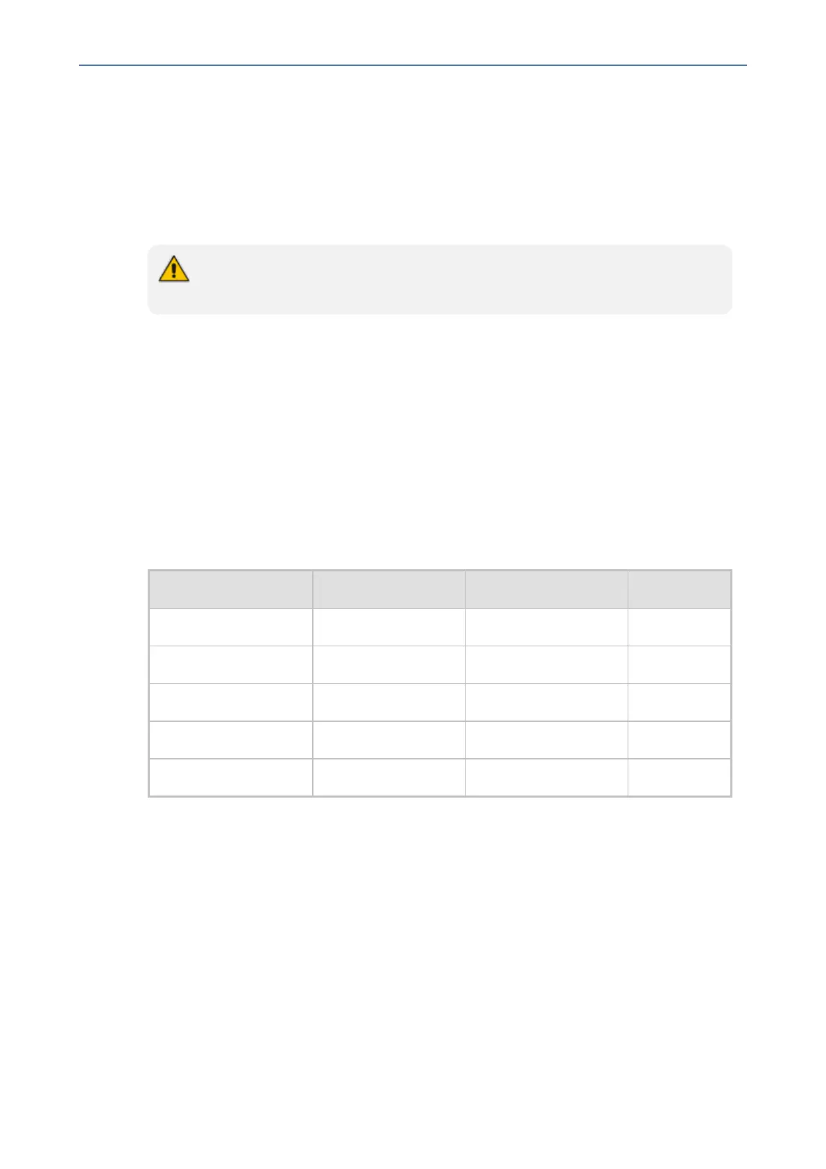
The following table describes the operational status of the dry-contact relays.
Table 5-1: Dry-Contact Relays Description
Operation Dry-Contact I State Dry-Contact II State STATUS LED
No Power Normally Open (NO) Normally Closed (NC) Off
No Alarm Open Open Solid Green
Minor Severity Alarm Closed Open Solid Orange
Major Severity Alarm Closed Closed Solid Red
Critical Severity Alarm Open Closed Solid Red
If the dry-contact relay is short-circuited (for whatever reason), the device sends the SNMP
alarm, acUserInputAlarm. For more information, refer to the SNMP Reference Guide.
Cabling specifications:
■ Connector: (Not Supplied) Dry-contact wires mate, consisting of a four spring-cage
pluggable terminal block connector, as shown in the following figure. The connections
correspond to the four pins of the dry-contact connector on the CRMX module.
- 50 -

 Loading...


