13
5.0 performance tests
5.2 Performance test procedure
For test point (TP) references, see section 6.0 Test Points.
No
5.2.10.
5.2.11.
5.2.12.
5.2.13.
5.2.14.
Action
Set up
amplifier for
1 W output
Measure signal
to noise ratio
(SNR)
Measure
distortion at
20 kHz
Measure
distortion at
100 Hz
Left channel
check
operation of
protection
circuit
Test Equipment
Audio Analyser
output: 1kHz,
500 mV
Audio Analyser
200Hz HP filter off
A-weighted filter on
Audio Analyser
output: 20kHz, 1 V,
200Hz HP filter on
A-weighted filter off
Audio Analyser
output: 100Hz, 1V
200Hz filter off
A-weighted filter off
Audio Analyser
output:
1 kHz, 100 mV
Oscilloscope
ch1: 0.5 V/div
0.2 Vms/div
ch2: 0.2 V/div
0.2 ms/div
trigger: ch1
Details
Adjust VOLUME knob until voltage on
output of amplifier is
2.83 V rms (or 1 W). If possible, set this
as 0 dB reference.
Remove input leads and replace with
shorted phono plugs.
Measure dB reading (if function is
available), which is equivalent to signal-
to-noise ratio.
Alternatively measure noise voltage and
calculate SNR.
SNR should be >80 dB.
SNR = 10 log
10
signal power
noise power
SNR = 20 log
10
signal voltage
noise voltage
Adjust the VOLUME knob to give
20 V rms at loudspeaker output.
Distortion should be <0.07% for left and
right channels.
Distortion should be <0.007% for left and
right channels.
Turn VOLUME knob to minimum.
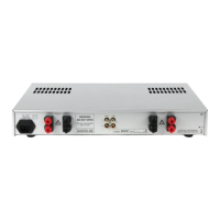
Connect ground clip of oscilloscope
probe to 0 V (TP 0).
Connect probe for channel 2 to cathode
of D943 (TP 11).
Short circuit loudspeaker terminal.
Slowly increase VOLUME. Check
oscilloscope traces with Figure 5.2.
Trace will appear briefly and will
disappear when amplifier mutes.