6. Electrical connection
6.1. Basic information
Electric shock due to presence of hazardous voltage!
Risk of death or serious injury!
→
The electrical connection must be carried out exclusively by suitably qualified
personnel.
→
Prior to connection, observe basic information contained in this chapter.
→
After connection but prior to applying the voltage, observe the <Commissioning>
and <Test run> chapters.
Wiring diagram/terminal
plan
The pertaining wiring diagram/terminal plan (in German or English) is attached to
the device in a weather-proof bag, together with these operation instructions. It can
also be requested from AUMA (state order number, refer to name plate) or
downloaded directly from the Internet (http://www.auma.com).
Permissible networks
(supply networks)
The actuators are suitable for use in TN and TT networks with directly grounded star
point for nominal voltages up to maximum 690 V AC. Use in IT network is permissible
for nominal voltages up to maximum 600 V AC. For IT network, a suitable, approved
insulation monitor measuring the pulse code is required.
Current type, mains
voltage, mains fre-
quency
Type of current, mains voltage and mains frequency must match the data on the
actuator controls and motor name plates. Also refer to chapter <Identification>/<Name
plate>.
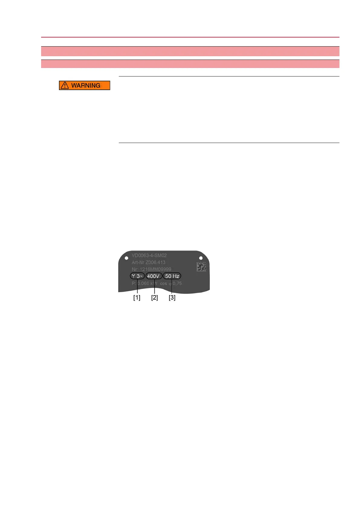
Figure 16: Motor name plate (example)
[1] Type of current
[2] Mains voltage
[3] Mains frequency
External supply of the
electronics
For external electronics supply, the power supply of actuator controls must have an
enhanced isolation against mains voltage in compliance with IEC 61010-1 and the
output power has to be limited to 150 VA in compliance with IEC 61010-1.
For external electronics supply with 24 V DC and simultaneous use of DC motors
(24 V DC, 48 V DC, 60 V DC, 110 V DC, 220 V DC), the 24 V DC actuator controls’
voltage supply should be ensured via the XK25/26 terminals, separately from the
power supply (U1, V1). In case of common supply using a single cable (links from
U1, V1 with XK25/26, for 24 V DC only!), short-term excess or falling below the
permissible voltage limits can be the consequence during switching (24 V DC +10
%/–10 %). Any possibly incoming operation commands are not executed outside
the admissible limit values.The actuator controls briefly signal a fault condition.
Protection and sizing on
site
For short-circuit protection and for disconnecting the actuator from the mains, fuses
and disconnect switches have to be provided by the customer.
The current values for sizing the protection can be derived from the current
consumption of the motor (refer to motor name plate) plus the current consumption
of actuator controls.
21
SQ 05.2 – SQ 14.2/SQR 05.2 – SQR 14.2 Control unit: electronic (MWG)
AC 01.2 Non-Intrusive Electrical connection

 Loading...