6.3. Accessories for electrical connection
6.3.1. Actuator controls on wall bracket
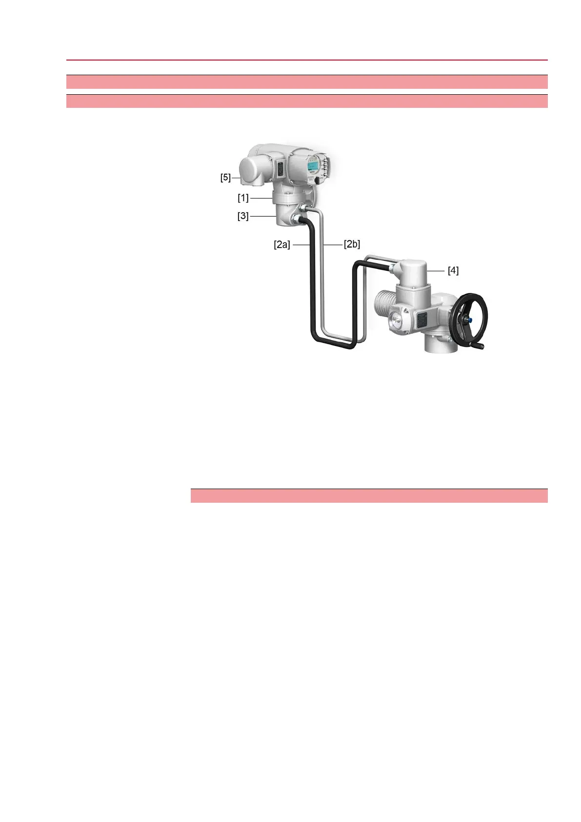
Design Figure 22: Design principle with wall bracket
[1] Wall bracket
[2] Connecting cables
[3] Electrical connection of wall bracket (XM)
[4] Electrical connection of actuator (XA)
[5] Elektroanschluss Steuerung (XK) – Kundenstecker
Application
The wall bracket allows separate mounting of actuator controls and actuator.
●
If the actuator cannot be accessed safely.
●
If the actuator is subjected to high temperatures.
●
In case of heavy vibration of the valve.
Information on installation with wall bracket
●
The permissible cable length between actuator controls on wall bracket and
the actuator amounts to 100 m maximum.
●
We recommend using an AUMA “LSW” cable set.
●
If the AUMA cable set is not used:
- Use suitable flexible and screened connecting cables.
- Use separate CAN bus cable of 120 Ohm character impedance for MWG
(e.g. UNITRONIC BUS-FD P CAN UL/CSA - 2 x 2 x 0.5 mm², manufacturer:
Lapp).
- Data cable connection: XM2-XA2 = CAN L, XM3-XA3 = CAN H.
- Voltage supply MWG: XM6-XA6 = GND, XM7-XA7 = + 24 V DC (refer to
wiring diagram).
●
For the electrical connection at wall bracket [3], the terminals are made as crimp
connections.
- Use a suitable four indent crimp tool for crimping.
- Cross sections for flexible wires:
- Control cables: max. 0.75 to 1.5 mm²
- Mains connection: max. 2.5 to 4 mm²
27
SQ 05.2 – SQ 14.2/SQR 05.2 – SQR 14.2 Control unit: electronic (MWG)
AC 01.2 Non-Intrusive Electrical connection

 Loading...