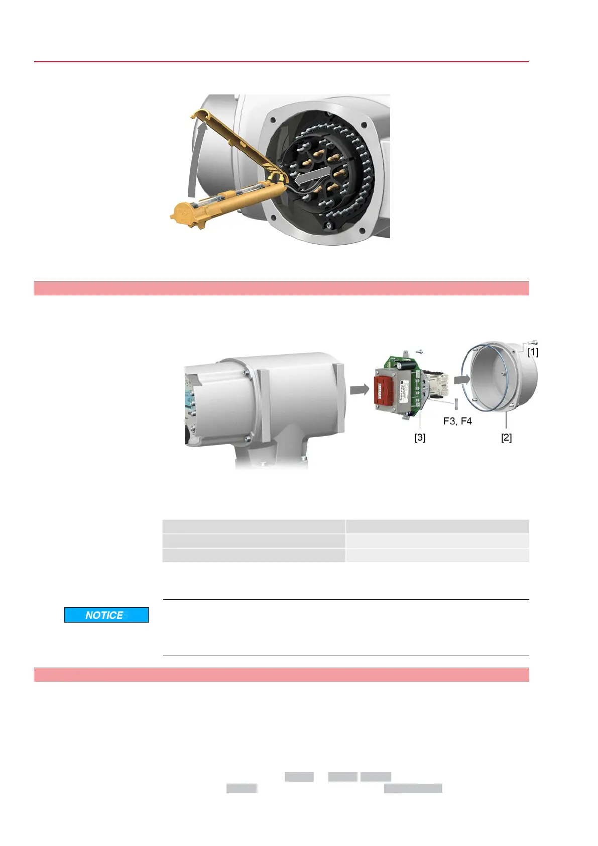
Figure 69:
2. Pull fuse holder out of pin carrier, open fuse cover and replace old fuses by
new ones.
12.3.2.2. Test/replace fuses F3/F4
1. Loosen screws [1] and remove cover [2] on the rear of the actuator controls.
Figure 70:
Check fuses.
2. The power supply unit has measuring points (solder pins) allowing to perform
a resistance (continuity) measurement:
Table 31:
Measuring pointsChecking
MTP5 – MTP6F3
MTP7 – MTP8F4
3. To replace defective fuses: Carefully loosen power supply unit [3] and pull out.
(The fuses are on the equipped part of the power supply board.)
Cable damage due to pinching!
Risk of functional failures.
→
Carefully assemble power supply unit to avoid pinching the cables.
12.3.3. Motor protection (thermal monitoring)
In order to protect against overheating and impermissibly high surface temperatures
at the actuator, PTC thermistors or thermoswitches are embedded in the motor
winding. Motor protection trips as soon as the max. permissible winding temperature
has been reached.
The actuator is switched off and the following signals are given:
●
LED 3 (motor protection trippped) on the local controls is illuminated.
●
The status indications S0007 or S0011 Failure display a fault.
The fault Details is displayed when selecting Thermal fault.
66
SQ 05.2 – SQ 14.2/SQR 05.2 – SQR 14.2 Control unit: electronic (MWG)
Corrective action AC 01.2 Non-Intrusive

 Loading...