2.
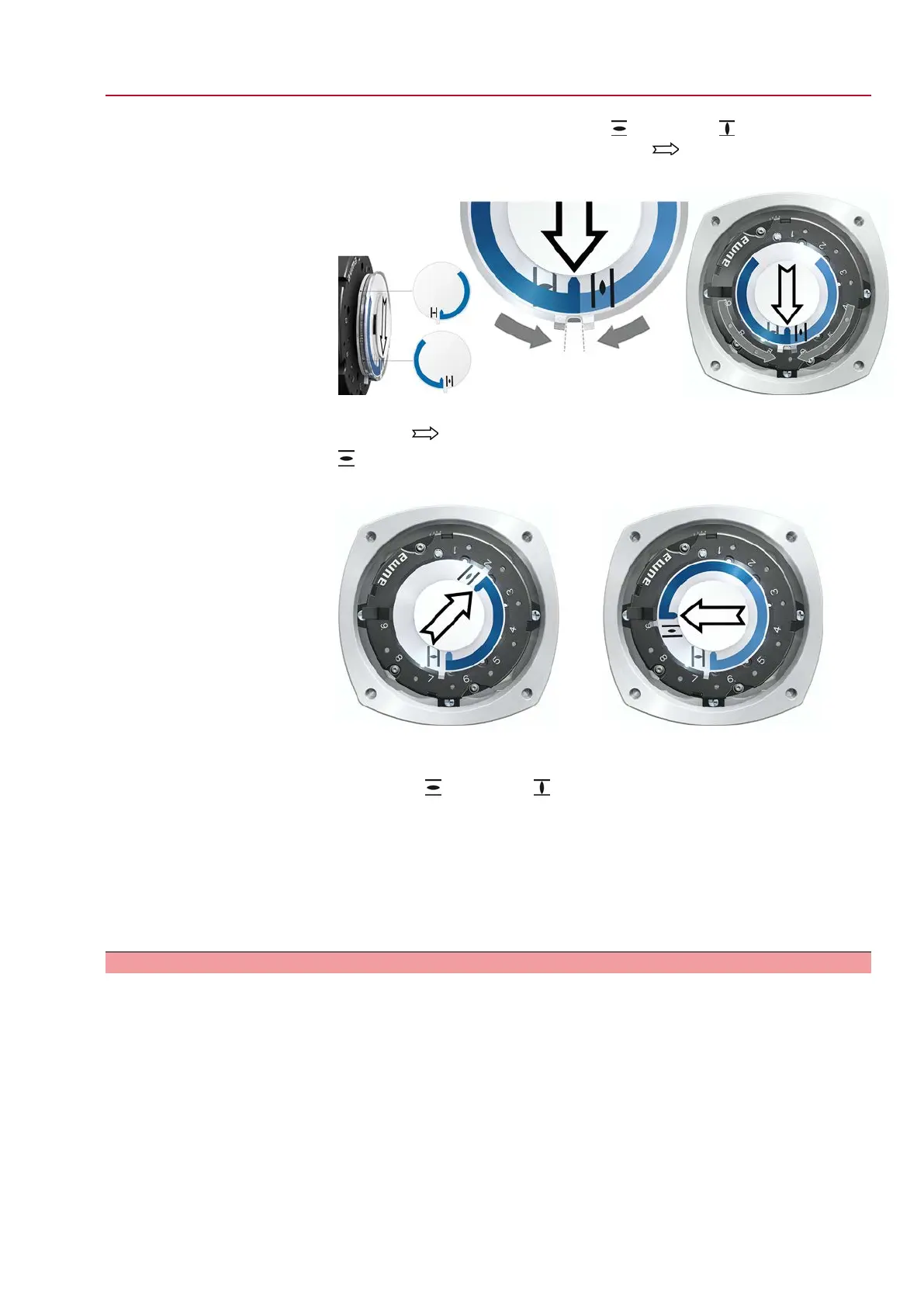
Push both lower discs with the symbols (OPEN) and (CLOSED) towards
each other. The disc with the arrow is thereby is driven:
Figure 64: Setting position in CLOSED
3. Move actuator to end position OPEN.
➥
The arrow rotates in direction OPEN driving the indicator disc with symbol
(OPEN) until the actuator stops in position OPEN.
Figure 65: Operation in direction OPEN (left) and position OPEN (right)
4. Check settings:
➥
The setting of the mechanical position indicator is correct if the angle between
the symbols (OPEN) and (CLOSED) ranges between approx. 120° and
280°.
➥
If all three discs are turned at the same time, the indicator can be shifted in
steps of 15°. Individual shifts of 5° are possible.
➥
If the indicator is rotated too far (more than 280°) or if the angle is too small
(below 120°), adapt the gear stage setting to the actuator swing angle. Refer
to <Gear stage of the reduction gearing: test/set>.
11.2.2. Gear stage of the reduction gearing: test/set
The test/setting is only required if the mechanical position indicator cannot be correctly
set or if another swing angle range is ordered subsequently, for example, 120° ±15°
instead of 90° ±15° (replacement by the AUMA Service only).
57
SQ 05.2 – SQ 14.2/SQR 05.2 – SQR 14.2 Control unit: electronic (MWG)
AC 01.2 Non-Intrusive Commissioning (settings in the actuator)

 Loading...