4. Assembly
4.1. Mounting position
AUMA actuators can be operated without restriction in any mounting position.
4.2. Handwheel fitting
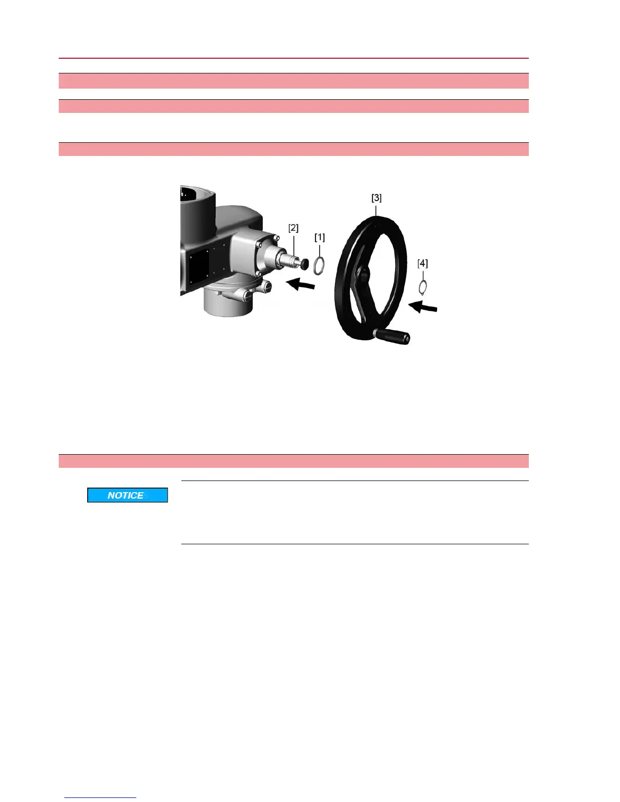
Figure 5: Handwheel
[1] Spacer
[2] Input shaft
[3] Handwheel
[4] Circlip
1. If required, fit spacer [1] onto input shaft [2].
2. Slip handwheel [3] onto input shaft.
3. Secure handwheel [3] using the circlip [4] supplied.
4.3. Actuator: mount to valve
Danger of corrosion due to damage to paint finish and condensation!
→
Touch up damage to paint finish after work on the device.
→
After mounting, connect the device immediately to electrical mains to ensure
that heater minimises condensation.
The actuator is mounted to the valve using a coupling (standard) or via lever. Separate
instructions are available for actuator mounting to the valve when equipped with
base and lever.
10
SQ 05.2 – SQ 14.2/SQR 05.2 – SQR 14.2
Assembly

 Loading...