3. If the end position setting is correct and no options (e.g. potentiometer, position
transmitter) are available: Close switch compartment.
9.7. Electronic position transmitter EWG 01.1
— Option —
The electronic position transmitter EWG 01.1 signals the remote position or the valve
position. On the basis of the actual valve position sensed by hall sensor, a current
signal between 0 – 20 mA or 4 – 20 mA is generated.
Technical data
Table 4: EWG 01.1
2-wire system3-wire or 4-wire systemData
4 – 20 mA0 – 20 mA, 4 – 20 mAOutput current I
a
24 V DC (18 – 32 V)24 V DC (18 – 32 V)Power supply U
V
1)
20 mALED off = 26 mA, LED on = 27
mA
Max. current consumption
(U
V
– 12 V)/20 mA
600 Ω
Max. load R
B
0.1 %Impact of power supply
0.1 %Load influence
< 0.1 ‰/KTemperature impact
–60 °C to +80 °CAmbient temperature
2)
Power supply possible via: AC, AM controls or external power supply1)
Depending on temperature range of the actuator: Refer to name plate2)
Setting elements
The EWG is housed in the actuator switch compartment. The switch compartment
must be opened to perform any settings. ➔ Refer to <Switch compartment: open>.
All settings are made via the two push buttons [S1] and [S2].
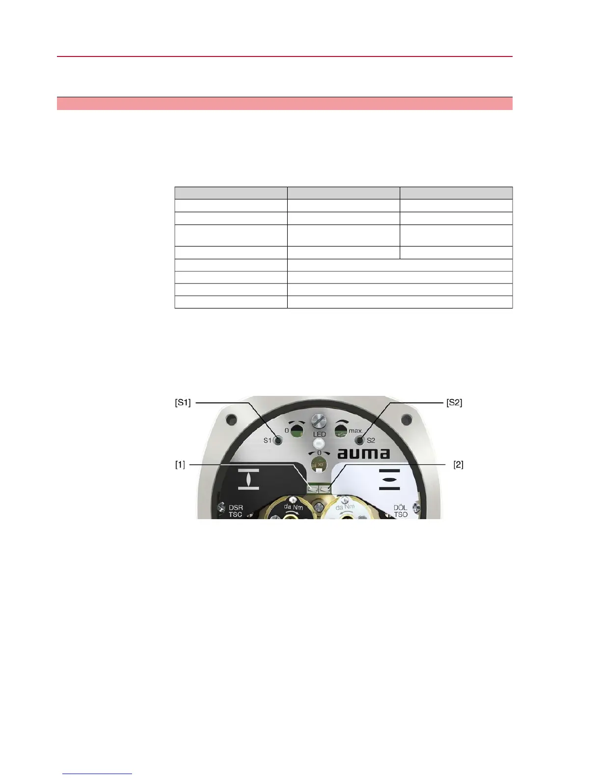
Figure 20: View on control unit when switch compartment is open
[S1] Push button: Set 0/4 mA
[S2] Push button: Set 20 mA
LED Optical aid for setting
[1] Measuring point (+) 0/4 – 20 mA
[2] Measuring point (–) 0/4 – 20 mA
The output current (measuring range 0 – 20 mA) can be checked at measuring points
[1] and [2].
28
SQ 05.2 – SQ 14.2/SQR 05.2 – SQR 14.2
Commissioning

 Loading...