4.3.1. Valve attachment via coupling
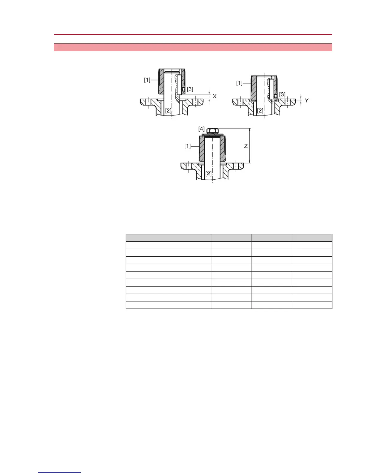
Dimensions Figure 6: Coupling fitting dimensions
[1] Coupling
[2] Valve shaft
[3] Grub screw
[4] Screw
Table 2: Coupling fitting dimensions
Z max [mm]Y max [mm]X max [mm]Type, size - output mounting flange
4023SQ/SQR 05.2-F05/F07
4023SQ/SQR 07.2-F05/F07
6623SQ/SQR 07.2-F10
5054SQ/SQR 10.2-F10
8254SQ/SQR 10.2-F12
61105SQ/SQR 12.2-F12
101105SQ/SQR 12.2-F14
75108SQ/SQR 14.2-F14
125108SQ/SQR 14.2-F16
Assembly
Information: Mount valve and actuator in the same end position.
- For butterfly valves: Recommended mounting position is end position
CLOSED.
- For ball valves: Recommended mounting position is end position OPEN.
1. Thoroughly degrease mounting faces of output mounting flanges.
2. Apply a small quantity of grease to the valve shaft [2].
3. Use handwheel to run actuator to mechanical end stop.
4. Place coupling [1] onto valve shaft [2] and secure against axial slipping by using
a grub screw, a circlip or a screw.Thereby, ensure that dimensions X, Y or Z
are observed (refer to figure and table <Coupling fitting dimensions>).
5. Apply non-acidic grease at splines of coupling.
6. Fit actuator.
Information: Ensure that the spigot (if provided) fits uniformly in the recess
and that the flanges are in complete contact.
7. If flange bores do not match thread:
7.1 Slightly rotate handwheel until bores line up.
7.2 If required, shift actuator position by one tooth on the coupling.
11
SQ 05.2 – SQ 14.2/SQR 05.2 – SQR 14.2
Assembly

 Loading...