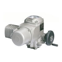
Figure 7: Motor name plate (example)
[1] Type of current
[2] Mains voltage
[3] Mains frequency (for 3-ph and 1-ph AC motors)
Connecting cables
●
For device insulation, appropriate (voltage-proof) cables must be used. Specify
cables for the highest occurring rated voltage.
●
Use connecting cable with appropriate minimum rated temperature.
●
For connecting cables exposed to UV radiation (outdoor installation), use UV
resistant cables.
5.2. Connection with AUMA plug/socket connector
Cross sections AUMA plug/socket connector:
●
Power terminals (U1, V1, W1, U2, V2, W2): max. 6 mm² flexible/10 mm² solid
●
PE connection : max. 6 mm² flexible/10 mm² solid
●
Control contacts (1 to 50): max. 2.5 mm²
5.2.1. Terminal compartment: open
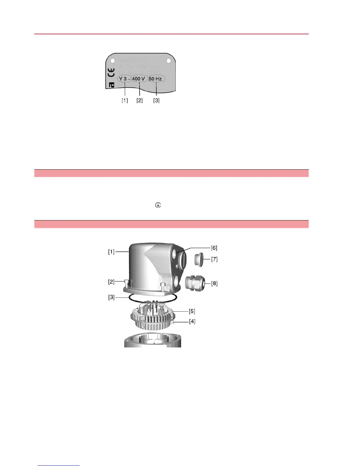
Figure 8: Connection AUMA plug/socket connector, version S
[1] Cover
[2] Screws for cover
[3] O-ring
[4] Screws for socket carrier
[5] Socket carrier
[6] Cable entry
[7] Blanking plug
[8] Cable gland (not included in delivery)
14
SQ 05.2 – SQ 14.2/SQR 05.2 – SQR 14.2
Electrical connection

 Loading...