5.3.1. Overview of output drive types
Table 10: Overview on output drive types
AssemblyDescriptionApplicationValve attachment
➭ page 18, Multi-turn actuator with
output drive type A: mount
➭ page 17, Output drive type A
●
for rising, non-rotating valve stem
●
capable of withstanding thrust
●
not appropriate for radial forces
A
➭ page 22, Multi-turn actuator with
output drive type B: mount
➭ page 21, Output drive types B/C/D
and E
●
for rotating, non-rising valve stem
●
not capable of withstanding thrust
B, B1 – B4
C
D
E
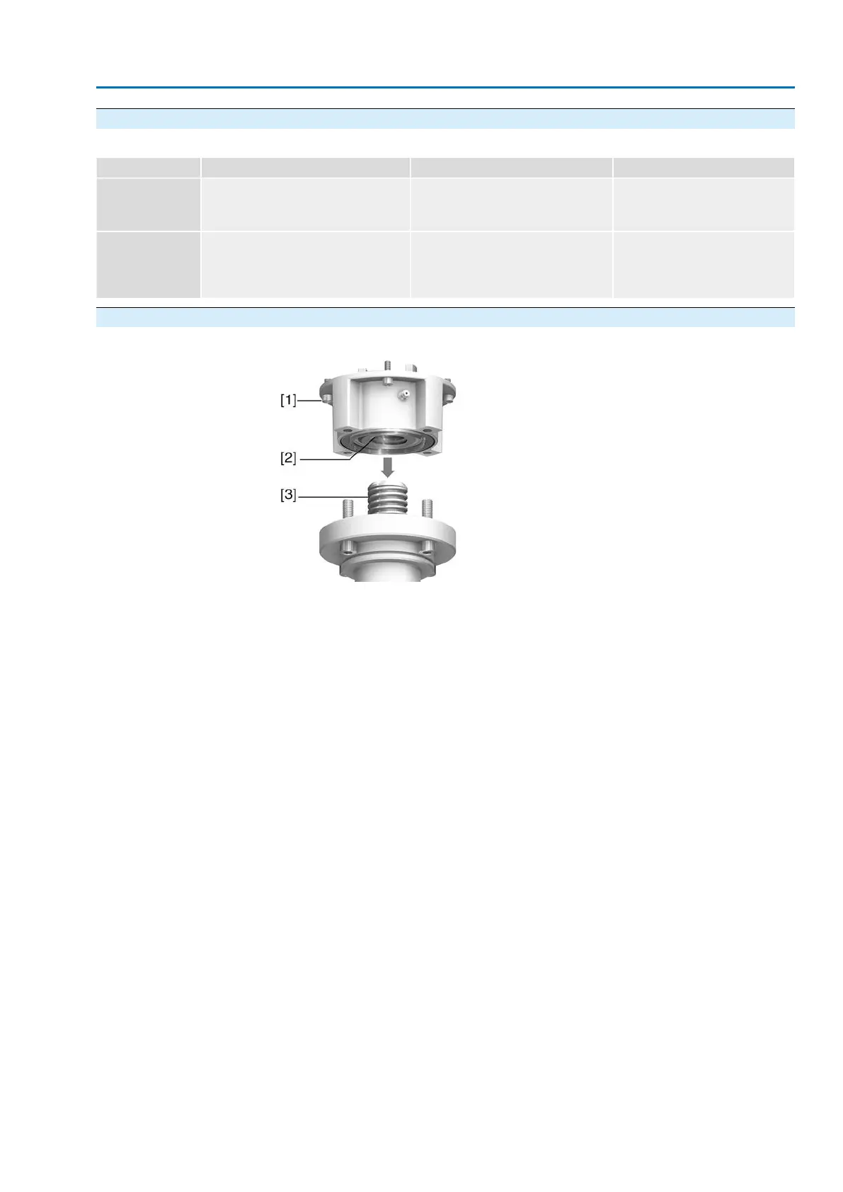
5.3.2. Output drive type A
Figure 11: Output drive type A
[1] Output mounting flange
[2] Stem nut
[3] Valve stem
Short description
Output drive type A consisting of output mounting flange [1] with axial bearing stem
nut [2].The stem nut transmits the torque from the actuator hollow shaft to the valve
stem [3]. Output drive type A can withstand thrusts.
To adapt the actuators to available output drive types A with flanges F10 and F14
(year of manufacture 2009 and earlier), an adapter is required.The adapter can be
ordered from AUMA.
17
SA 07.2 – SA 16.2/SAR 07.2 – SAR 16.2 Control unit - electromechanical
AC 01.2 Intrusive Modbus RTU Assembly

 Loading...


