5.3.2.2. Stem nut for output drive type A: finish machining
This working step is only required if stem nut is supplied unbored or with pilot bore.
Information For exact product version, please refer to the order-related technical data sheet or
the AUMA Assistant App.
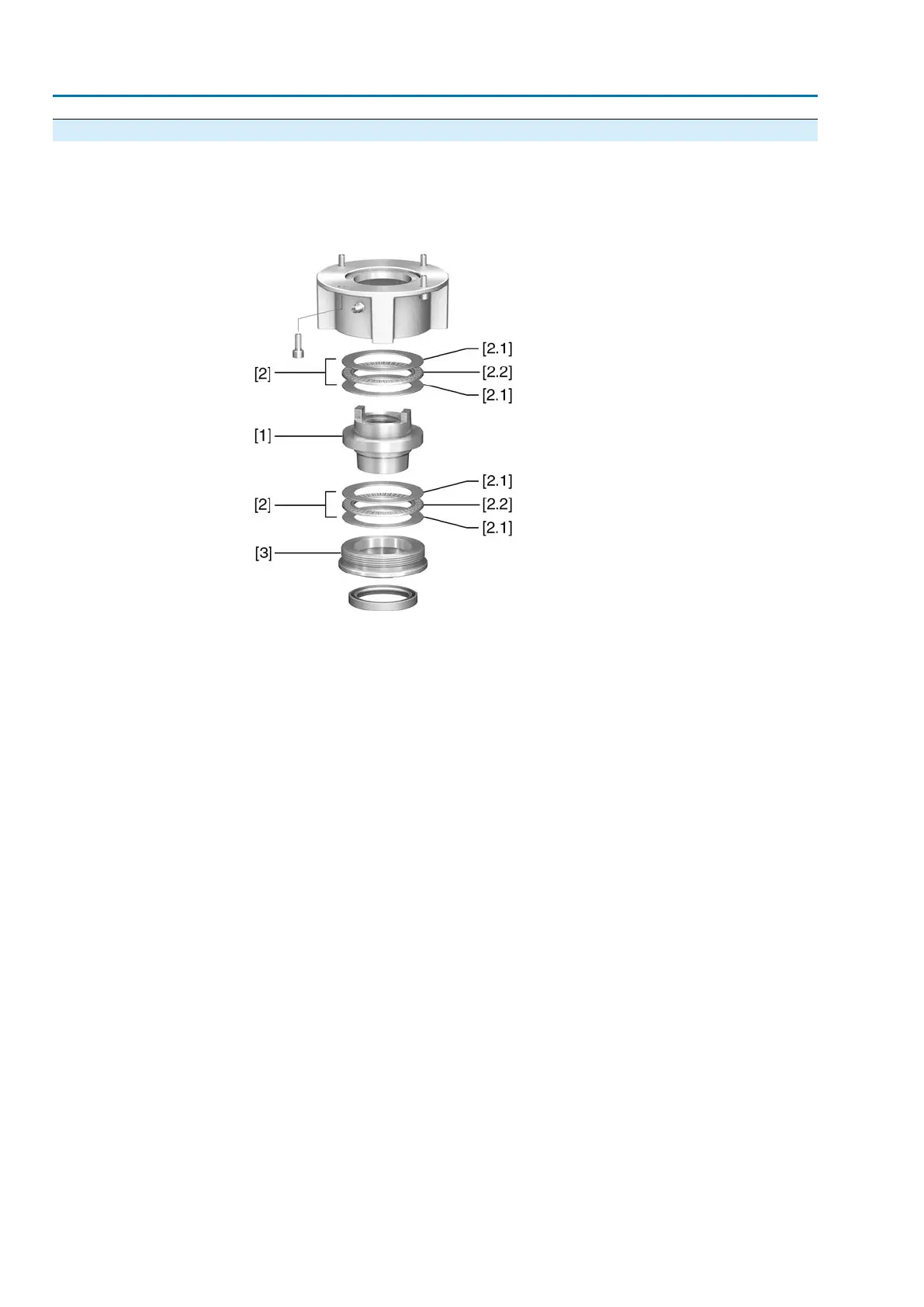
Figure 16: Output drive type A
[1] Stem nut
[2] Axial needle roller bearing
[2.1] Axial bearing washer
[2.2] Axial needle roller and cage assembly
[3] Spigot ring
Procedure
1. Remove spigot ring [3] from output drive.
2. Remove stem nut [1] together with axial needle roller bearings [2].
3. Remove axial bearing washers [2.1] and axial needle roller and cage assemblies
[2.2] from stem nut [1].
4. Drill and bore stem nut [1] and cut thread.
5. Clean the machined stem nut [1].
6. Apply sufficient Lithium soap EP multi-purpose grease to axial needle roller and
cage assemblies [2.2] and axial bearing washers [2.1], ensuring that all hollow
spaces are filled with grease.
7. Place greased axial needle roller and cage assemblies [2.2] and axial bearing
washers [2.1] onto stem nut [1].
8. Re-insert stem nut [1] with axial needle roller bearings [2] into output drive.
9. Screw in spigot ring [3] until it is firm against the shoulder.
20
SA 07.2 – SA 16.2/SAR 07.2 – SAR 16.2 Control unit - electromechanical
Assembly AC 01.2 Intrusive Modbus RTU

 Loading...


