9.6 Potentiometer setting
— Option —
The potentiometer as travel sensor records the valve position.
Information Due to the ratio of the reduction gearing the complete resistance range/stroke is not
always passed.Therefore, external adjustment (setting potentiometer) must be pro-
vided.
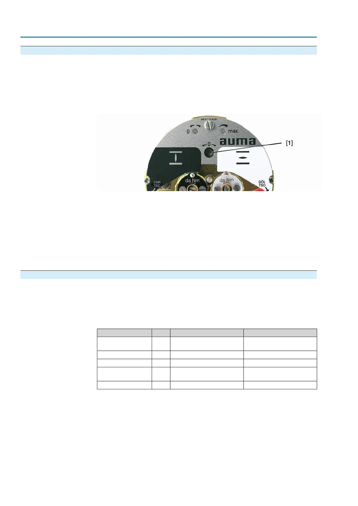
Figure 31: View of control unit
[1] Potentiometer
1. Move valve to end position CLOSED.
2. Turn potentiometer [1] clockwise to the stop.
➥
End position CLOSED corresponds to 0 %
➥
End position OPEN corresponds to 100 %
3. Turn potentiometer [1] slightly in opposite direction.
4. Perform fine-tuning of the zero point at external setting potentiometer (for remote
indication).
9.7 Electronic position transmitter RWG: set
— Option —
The electronic position transmitter RWG records the valve position. On the basis of
the actual position value measured by the potentiometer (travel sensor), it generates
a current signal between 0 – 20 mA or 4 – 20 mA.
Table 4: Technical data RWG 4020
2-wire system3- or 4-wire systemWiring
TP_ 4 _/ _ _ _
TP_ 5 _/ _ _ _
TP_ _4/ _ _ _KMSTerminal plan
4 – 20 mA0 – 20 mA, 4 – 20 mAI
A
Output current
14 V DC +(I x R
B
), max. 30 V24 V DC, ±15 % smoothedU
V
Power supply
20 mA24 mA at 20 mA output currentIMax. current consump-
tion
(U
V
– 14 V) /20 mA
600 Ω
R
B
Max. load
30
SA 25.1 – SA 48.1/SAR 25.1 – SAR 30.1
Commissioning