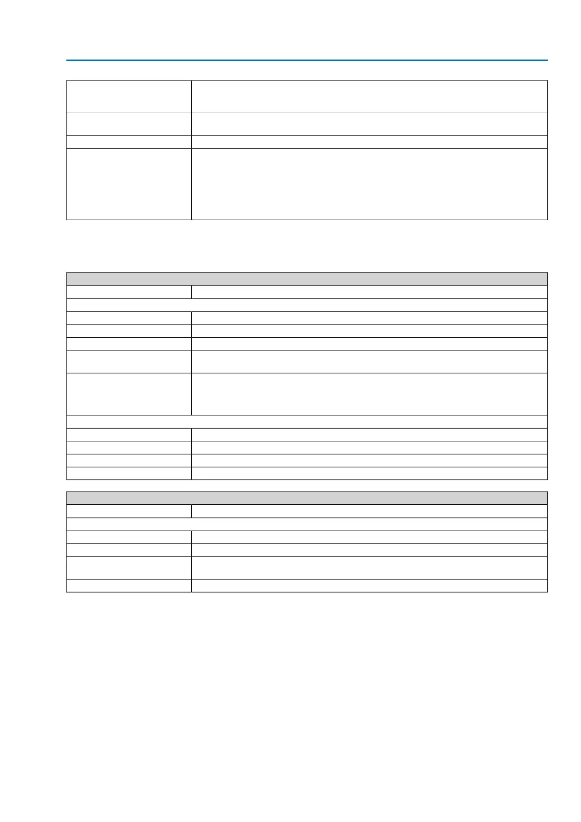
Standard: AUMA plug/socket connector with screw-type connection
Options: Terminals or crimp connection
Motor connection on separate terminals
Electrical connection
Standard: Metric threads
Options: Pg-threads, NPT-threads, G-threads
Threads for cable entries
Terminal plan according to commission number attached with deliveryTerminal plan
Standard: B1 according to EN ISO 5210
Options:
A, B2, B3, B4 according to EN ISO 5210
A, B, D, E according to DIN 3210
C according to DIN 3338
Special output drive types: AF, B3D, ED, DD, (IB1 or IB3 only size 25.1)
A with stem lubrication
Valve attachment
For nominal voltage and 40 °C ambient temperature and an average load with running torque or modulating torque according to sepa-
rate technical data.The type of duty must not be exceeded.
1)
PTC thermistors additionally require a suitable tripping device within the controls2)
Technical data for limit and torque switches
2 x 10
6
startsMechanical lifetime
Silver plated contacts:
30 V AC/DCU min.
250 V AC/DCU max.
20 mAI min.
5 A at 250 V (resistive load)
3 A at 250 V (inductive load, cos phi = 0.6)
I max. AC current
0.4 A at 250 V (resistive load)
0.03 A at 250 V (inductive load, L/R = 3 µs)
7 A at 30 V (resistive load)
5 A at 30 V (inductive load, L/R = 3 µs)
I max. DC current
Gold plated contacts:
5 VU min.
30 VU max.
4 mAI min.
400 mAI max.
Technical data for blinker transmitter
10
7
startsMechanical lifetime
Silver plated contacts:
10 V AC/DCU min.
250 V AC/DCU max.
3 A at 250 V (resistive load)
2 A at 250 V (inductive load, cos phi ≈ 0.8)
I max. AC current
0.25 A at 250 V (resistive load)I max. DC current
37
SA 25.1 – SA 48.1/SAR 25.1 – SAR 30.1
Technical data