5.2.5. Fieldbus cables: connect
RS-485 connection
boards
Table 15:
AUMA art. no.
on label
1)
Overvoltage
protection up to 4 kV
Variant
Z071.720/02No1 channel (standard)
Z071.720/04Yes1 channel
Z071.720/03No2-channel for line redundancy
Z071.720/05Yes2-channel for line redundancy
Z102.613/01No2-channel for loop redundancy
Z102.613/02Yes2-channel for loop redundancy
Label with article number on connection board1)
Figure 26: Variants of connection boards
n–1 Fieldbus cable from previous device (input)
n+1 Fieldbus cable to next device (output)
[X] Shielding clamp
[X...] Terminal designation (X1, X2, X3, X4) according to wiring diagram
[S1/2] "Termination" switch for fieldbus termination
Table 16:
Functions of switches [S1] and [S2]
1)2)
Fieldbus termination channel 1 ONON[S1]
Fieldbus termination channel 1 OFFOFF
Fieldbus termination channel 2 ON (option)ON[S2]
Fieldbus termination channel 2 OFF (option)OFF
Upon delivery, the switches [S1] and [S2] are set to position OFF.1)
For loop redundancy, automatic termination is performed as soon as actuator controls are connected
to the power supply.When interrupting the power supply, e.g. after removing the AUMA plug/socket
connector, both RS-485 loop segments are automatically connected to each other.
2)
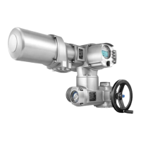
Cable connection
1. Always link A connections to green wire and B connections to red wire.
31
SAV 07.2 – SAV 16.2 / SARV 07.2 – SARV 16.2 Control unit: electronic (MWG)
ACV 01.2 Modbus RTU Electrical connection

 Loading...