5.3.2 Cable connection
Table 6: Terminal cross sections and tightening torques
Tightening torquesTerminal cross sectionsType
1.5 – 1.8 Nmmax. 10 mm² (flexible or solid)Power terminals (U, V, W)
3.0 – 4.0 Nmmax. 10 mm² (flexible or solid)PE connection
0.6 – 0.8 Nmmax.2.5 mm² (flexible or solid)Control contacts (1 to 50)
1. Strip wires.
2. For flexible cables: Use end sleeves according to DIN 46228.
3. Connect cables according to order-related wiring diagram.
In case of a fault: Hazardous voltage while protective earth conductor is NOT
connected!
Risk of electric shock.
→
Connect all protective earth conductors.
→
Connect PE connection to external protective earth conductor of connecting
cables.
→
Start running the device only after having connected the protective earth con-
ductor.
4. Tighten protective earth firmly to PE connection
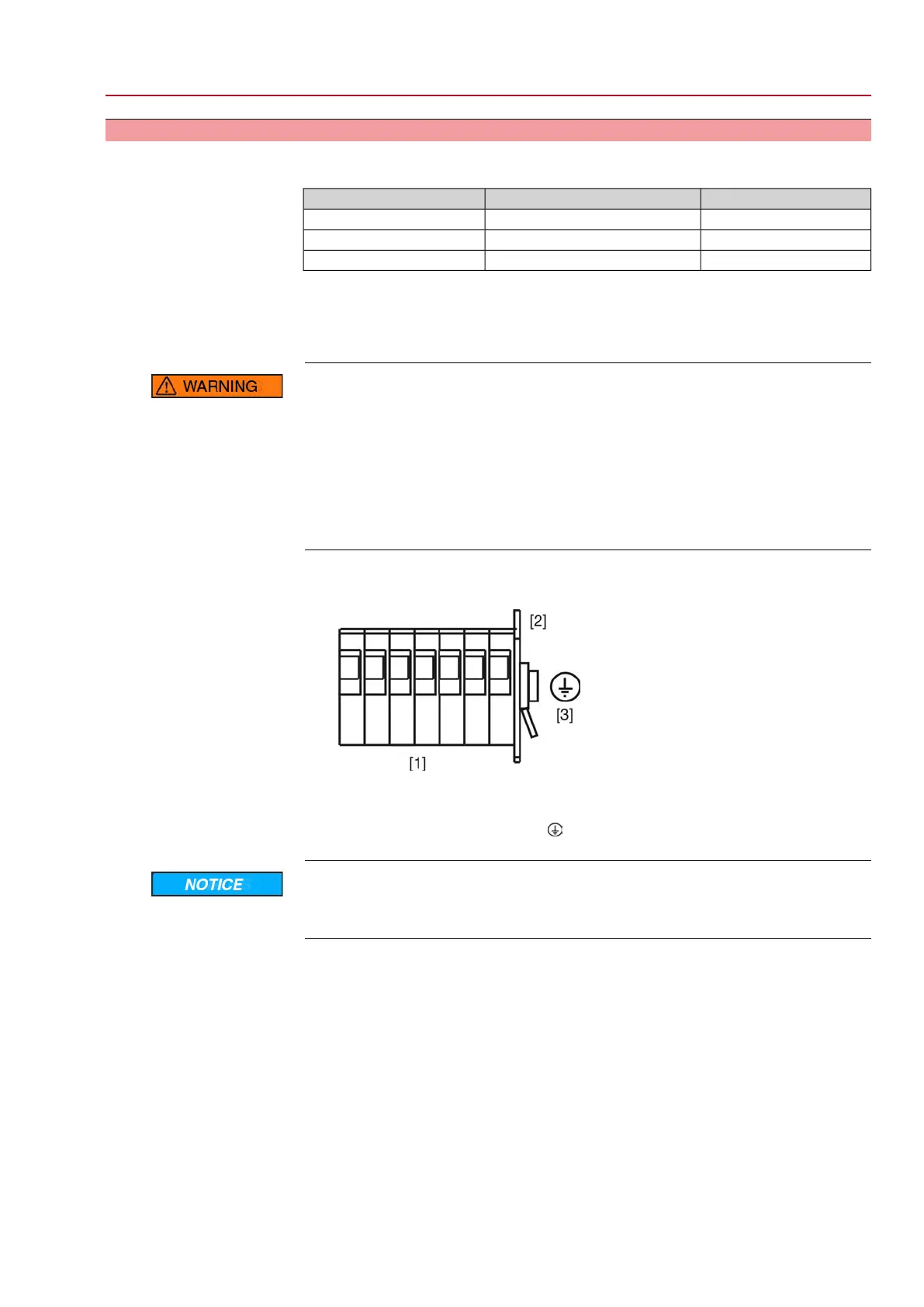
Figure 19: PE connection
[1] Terminal blocks
[2] Terminal housing
[3]
PE connection, symbol:
Danger of corrosion: Damage due to condensation!
→
After mounting, commission the device immediately to ensure that heater mini-
mises condensation.
Information Some actuators are equipped with an additional motor heater. The motor heater
minimises condensation within the motor and improves the start-up behaviour for
extremely low temperatures.
23
SGExC 05.1 – SGExC 12.1 Control unit: electromechanic
ACExC 01.2 Intrusive Modbus RTU Electrical connection
 Loading...


