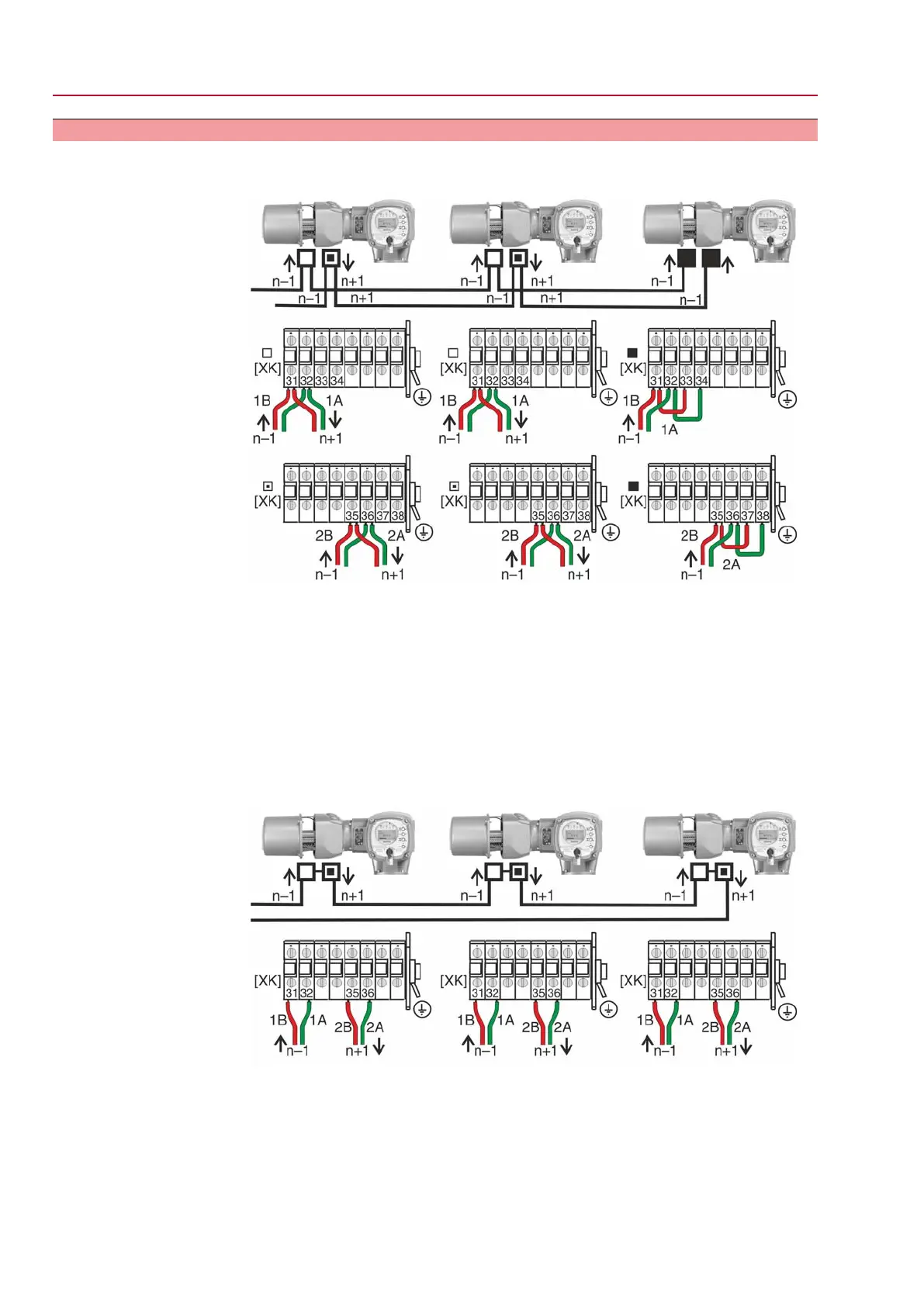
5.3.3 Bus cables: connect
Figure 20: Terminal assignment for line topology (1-channel or 2-channel for AUMA
redundancy I or II)
□
Channel 1: Further bus devices will follow (standard)
▣
Channel 2: Further bus devices will follow (AUMA redundancy I or II only)
■
Last bus device
n–1 Fieldbus cable from previous device (input)
n+1 Fieldbus cable to next device (output)
[XK] Terminal assignment according to wiring diagram (customer connection):
Channel 1: Terminals 31, 32 and 33, 34
Channel 2: Terminals 35, 36 and 37, 38 (AUMA redundancy I or II)
Figure 21: Terminal assignment for loop topology (2-channel)
□
Channel 1
▣
Channel 2
n–1 Fieldbus cable from previous device (input via channel 1)
n+1 Fieldbus cable to next device (input via channel 2)
[XK] Terminal assignment according to wiring diagram (customer connection)
24
SGExC 05.1 – SGExC 12.1 Control unit: electromechanic
Electrical connection ACExC 01.2 Intrusive Modbus RTU
 Loading...


