Information
●
For loop topology, automatic termination is performed as soon as the AUMATIC
is connected to the power supply.
●
In case of a power outage of the AUMATIC, the two RS-485 loop segments will
be automatically connected so that the actuators following these segments re-
main available.
●
When using a SIMA master station, a redundant loop topology may be establis-
hed.
Connecting bus cables:
1. Connect bus cables.
2. If the actuator is the final device in the bus segment (line topology only ):
2.1 Connect termination resistor for channel 1 through linking the terminals
31 - 33 and 32 - 34 (standard)
2.2 For AUMA redundancy I or II: Connect termination resistor for channel 2
through linking the terminals 35 - 37 and 36 - 38.
5.3.4 Terminal compartment: close
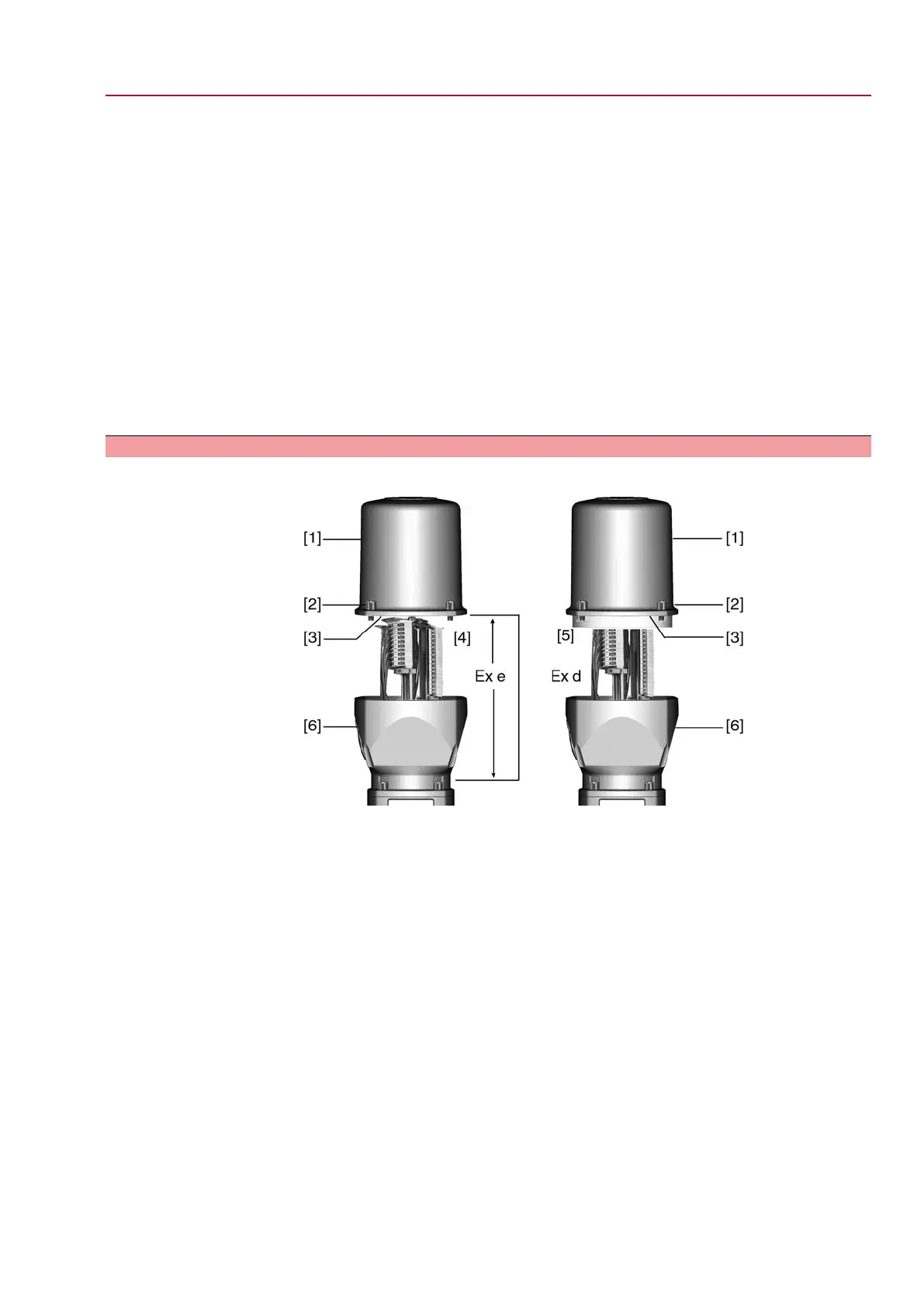
Figure 22: Plug/socket connector: left KES, right KES flameproof
[1] Cover
[2] Screws for cover
[3] O-ring
[4] Terminal compartment: Type of protection Ex e
[5] Terminal compartment: Type of protection Ex d
[6] Frame
1. Clean sealing faces of cover [1] and housing.
2. Plug/socket connector designed as KES flameproof: Preserve joint surfaces
with an acid-free corrosion protection agent.
3. Check whether O-ring [3] is in good condition, replace if damaged.
4. Apply a thin film of non-acidic grease (e.g. petroleum jelly) to the O-ring and
insert it correctly.
25
SGExC 05.1 – SGExC 12.1 Control unit: electromechanic
ACExC 01.2 Intrusive Modbus RTU Electrical connection
 Loading...


