5.2 Connecting via plug/socket connector with screw-type terminals (KP, KPH)
5.2.1 Terminal compartment: open
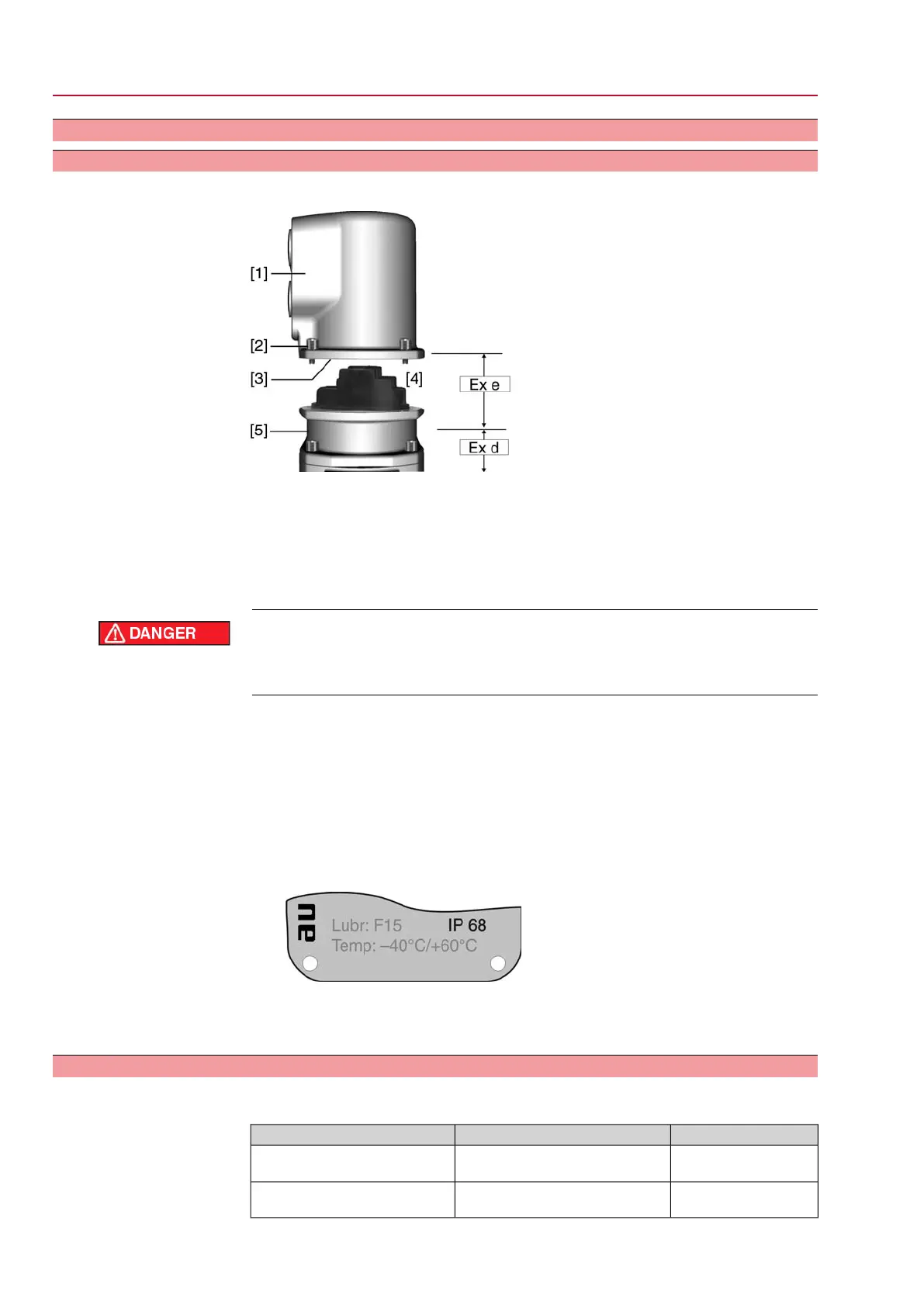
Figure 11: Plug/socket connector KPH
[1] Cover
[2] Screws for cover
[3] O-ring
[4] Terminal compartment
[5] Terminal board
Hazardous voltage!
Risk of electric shock.
→
Disconnect device from the mains before opening.
1. Loosen screws [2] and remove cover [1].
➥
Terminal compartment [4] is designed for explosion protection Ex e (increased
safety). The flameproof compartment (type of protection Ex d) remains hereby
closed.
2. Insert cable glands with Ex e approval and of size suitable for connection cables.
➥
The enclosure protection IP… stated on the name plate is only ensured if suita-
ble cable glands are used. Example: Name plate shows enclosure protection
IP 68.
3. Seal cable entries which are not used with approved plugs suitable for the re-
quired protection type.
4. Insert the wires into the cable glands.
5.2.2 Cable connection
Table 5: Terminal cross sections and tightening torques
Tightening torquesTerminal cross sectionsType
2 Nm(1.5)
1)
2.5 – 6 mm²
(flexible or solid)
Power terminals (U1, V1, W1)
PE connection
1 Nm0.75 – 1.5 mm²
(flexible or solid)
Control contacts (1 to 50)
18
SGExC 05.1 – SGExC 12.1 Control unit: electromechanic
Electrical connection ACExC 01.2 Intrusive Modbus RTU
 Loading...


