Figure 75: View of control unit
[1] Potentiometer
1. Move valve to end position CLOSED.
2. Turn potentiometer [1] counterclockwise until stop is felt.
➥
End position CLOSED corresponds to 0 %
➥
End position OPEN corresponds to 100 %
3. Turn potentiometer [1] slightly in opposite direction.
4. Perform fine-tuning of the zero point at external setting potentiometer (for remote
indication).
9.11 Electronic position transmitter RWG: set
— Option —
The electronic position transmitter RWG records the valve position. On the basis of
the actual position value measured by the potentiometer (travel sensor), it generates
a current signal between 0 – 20 mA or 4 – 20 mA.
Table 10: Technical data RWG 4020
3- or 4-wire systemWiring
9
th
position = E or HTPATerminal plan
0 – 20 mA, 4 – 20 mAI
A
Output current
24 V DC, ±15 % smoothedU
V
Power supply
24 mA at 20 mA output currentIMax. current consump-
tion
600 Ω
R
B
Max. load
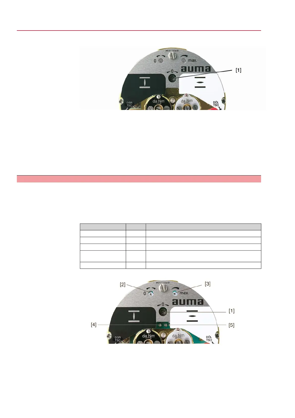
Figure 76: View of control unit
[1] Potentiometer (travel sensor)
[2] Potentiometer min. (0/4 mA)
[3] Potentiometer max. (20 mA)
[4] Measuring point (+) 0/4 – 20 mA
[5] Measuring point (–) 0/4 – 20 mA
1. Connect voltage to electronic position transmitter.
54
SGExC 05.1 – SGExC 12.1 Control unit: electromechanic
Commissioning (basic settings) ACExC 01.2 Intrusive Modbus RTU
 Loading...


