5.3.2. Cable connection
Table 14:
Terminal cross sections and terminal tightening torques
Tightening torquesTerminal cross sectionsDesignation
1.5 – 1.8 Nmmax. 10 mm² (flexible or solid)Power contacts (U, V, W)
3.0 – 4.0 Nmmax. 10 mm² (flexible or solid)PE connection
0.6 – 0.8 Nmmax. 2.5 mm² flexible, or
max. 4 mm² solid
Control contacts (1 to 50)
1. Remove cable sheathing and insert the wires into the cable glands.
2. Fasten cable glands with the specified torque to ensure required enclosure
protection.
Information: For shielded cables: Link the cable shield end via the cable gland
to the housing (earthing).
3. Strip wires.
4. For flexible cables: Use end sleeves according to DIN 46228.
5. Connect cables according to order-related wiring diagram.
In case of a fault: Hazardous voltage while protective earth conductor is NOT
connected!
Risk of electric shock.
→
Connect all protective earth conductors.
→
Connect PE connection to external protective earth conductor of connecting
cables.
→
Start running the device only after having connected the protective earth con-
ductor.
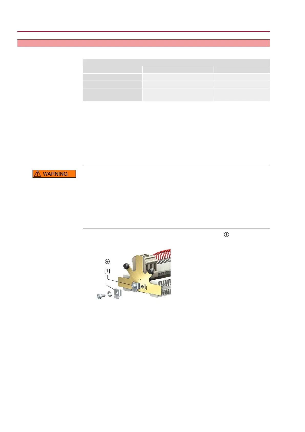
6.
Firmly tighten protective earth to PE connection (symbol: ).
Figure 24: Protective earth (PE)
[1] U-bracket for PE connection
30
SQEx 05.2 – SQEx 14.2 / SQREx 05.2 – SQREx 14.2 Control unit - electromechanical
Electrical connection ACExC 01.2 Intrusive

 Loading...