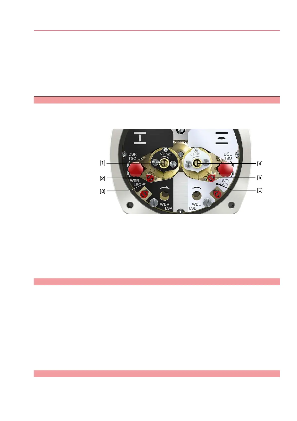
2. Turn torque dial [4] to set the required torque (1 da Nm = 10 Nm). Example:
-
Black torque switching head set to approx. 25 da Nm ≙ 250 Nm for direction
CLOSE
-
White torque switching head set to approx. 20 da Nm ≙ 200 Nm for direction
OPEN
3. Fasten lock screws [3] again.
Information: Maximum tightening torque: 0.3 – 0.4 Nm
➥
The torque switch setting is complete.
9.5. Limit switching: set
The limit switching records the travel. When reaching the preset position, switches
are operated.
Figure 68: Setting elements for limit switching
Black section:
[1] Setting spindle: End position CLOSED
[2] Pointer: End position CLOSED
[3] Mark: End position CLOSED is set
White section:
[4] Setting spindle: End position OPEN
[5] Pointer: End position OPEN
[6] Mark: End position OPEN is set
9.5.1. End position CLOSED (black section): set
1. Engage manual operation.
2. Turn handwheel clockwise until valve is closed.
3. Press down and turn setting spindle [1] with screw driver in direction of the
arrow and observe the pointer [2]: While a ratchet click is felt and heard, the
pointer [2] moves 90° every time.
4. As soon as the pointer [2] is 90° from mark [3]: Continue turning slowly.
5. As soon as the pointer [2] moves to mark [3]: Stop turning and release setting
spindle.
➥
The end position CLOSED setting is complete.
6. If you override the tripping point inadvertently (ratchet click is heard after the
pointer has snapped): Continue turning the setting spindle in the same direction
and repeat setting process.
9.5.2. End position OPEN (white section): set
1. Engage manual operation.
2. Turn handwheel counterclockwise until valve is open.
61
SQEx 05.2 – SQEx 14.2 / SQREx 05.2 – SQREx 14.2 Control unit - electromechanical
ACExC 01.2 Intrusive Commissioning (basic settings)

 Loading...