11. Corrective action
11.1. Faults during commissioning
Table 26:
Faults during operation/commissioning
RemedyDescription/causeFault
Set gear stage of the reduction gearing.Reduction gearing is not suitable for actuator swing
angle.
Mechanical position indicator cannot
be set.
●
Determine overrun: Overrun = travel covered
from switching off until complete standstill.
●
Set limit switching again considering the over-
run. (Turn handwheel back by the amount of
the overrun)
The overrun was not considered when setting the
limit switching.
The overrun is generated by the inertia of both the
actuator and the valve and the delay time of the
actuator controls.
In spite of correct setting of mechan-
ical limit switching, actuator operates
into the valve or actuator end position.
Set gear stage of the reduction gearing.Reduction gearing is not suitable for turns/stroke
of the actuator.
Measuring range 0/4 – 20 mA or
maximum value 20 mA at position
transmitter cannot be set or supplies
an incorrect value.
Call service.The LED on the EWG either flashes in setting mode
a) single flash or b) triple flash:
a) EWG is not calibrated.
b) Magnet positions of EWG are not aligned.
The measuring range 0/4 – 20 mA at
EWG position transmitter cannot be
set.
Check setting, if required, reset end positions.
Refer to <Check switches> and replace the
switches if required.
Switch is defective or switch setting is incorrect.Limit and/or torque switches do not
trip.
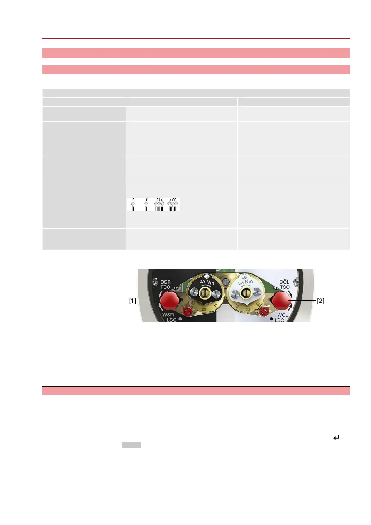
Switch check
The red test buttons [1] and [2] are used for manual operation of the switches:
1. Turn test button [1] in direction of the TSC arrow:Torque switch CLOSED trips.
2. Turn test button [2] in direction of the TSO arrow: Torque switch OPEN trips.
If the actuator is equipped with a DUO limit switching (option), the intermediate
position switches (LSA and LSB) will be operated at the same time as the torque
switches.
1. Turn test button [1] in direction of the LSC arrow: Limit switch CLOSED trips.
2. Turn test button [2] in direction of the LSO arrow: Limit switch OPEN trips.
11.2. Fault indications and warning indications
Faults interrupt or prevent the electrical actuator operation. In the event of a fault,
the display backlight is red.
Warnings have no influence on the electrical actuator operation.They only serve
for information purposes.The display remains white.
Collective signals include further indications.They can be displayed via the
Details push button.The display remains white.
71
SQEx 05.2 – SQEx 14.2 / SQREx 05.2 – SQREx 14.2 Control unit - electromechanical
ACExC 01.2 Intrusive Corrective action

 Loading...