5.6. Accessories for electrical connection
5.6.1. Actuator controls on wall bracket
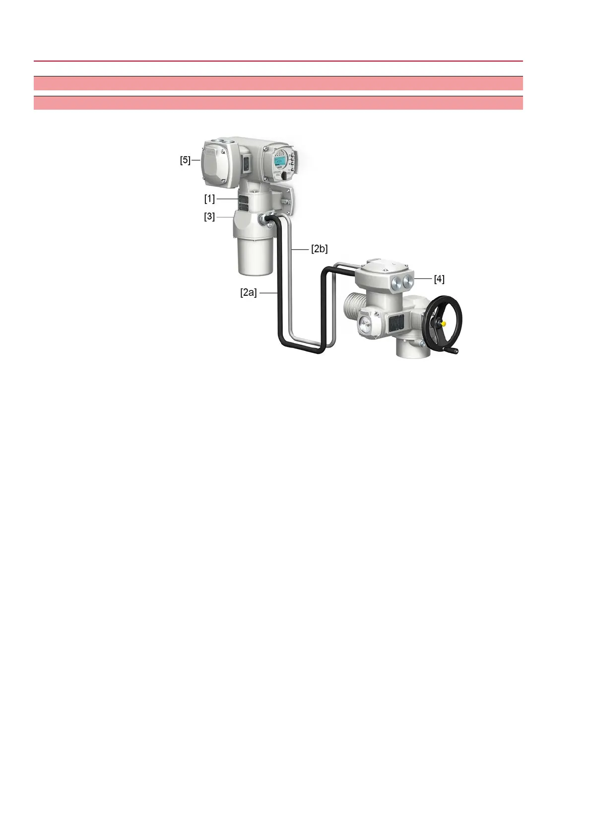
Design Figure 34: Design principle with wall bracket
[1] Wall bracket
[2] Connecting cables
[3] Electrical connection of wall bracket (XM)
[4] Electrical connection of actuator controls (XA)
[5] Electrical connection of actuator controls (XK) - customer plug
Application
The wall bracket allows separate mounting of actuator controls and actuator.
●
If the actuator cannot be accessed safely.
●
If the actuator is subjected to high temperatures.
●
In case of heavy vibration of the valve.
Observe prior to connec-
tion
●
Permissible length of connecting cables: max. 100 m.
●
If the actuator is equipped with a position transmitter (RWG): Connecting cables
must be available as shielded version.
●
Versions with potentiometer in the actuator are not suitable.
●
We recommend using an AUMA “LSW” cable set .
●
If the AUMA cable set is not used: Use suitable flexible and screened connecting
cables.
●
When using connecting cables, e.g. of the heater or switch, requiring direct
wiring from the actuator to the XK customer plug (XA-XM-XK, refer to wiring
diagram), these connecting cables must be subject to an insulation test in
compliance with EN 50178. Connecting cables of position transmitters (RWG,
IWG, potentiometer) do not belong to this group. They may not be subjected
to an insulation test.
38
SQEx 05.2 – SQEx 14.2 / SQREx 05.2 – SQREx 14.2 Control unit - electromechanical
Electrical connection ACExC 01.2 Intrusive

 Loading...