●
Signal state at input:
- DIN 4: Not active (triangle not filled in)
Low level = 0 V = No operation command in direction OPEN
- DIN 5: Active (triangle is black)
Low level = 0 V = EMERGENCY operation command is available
Diagnostic of digital outputs
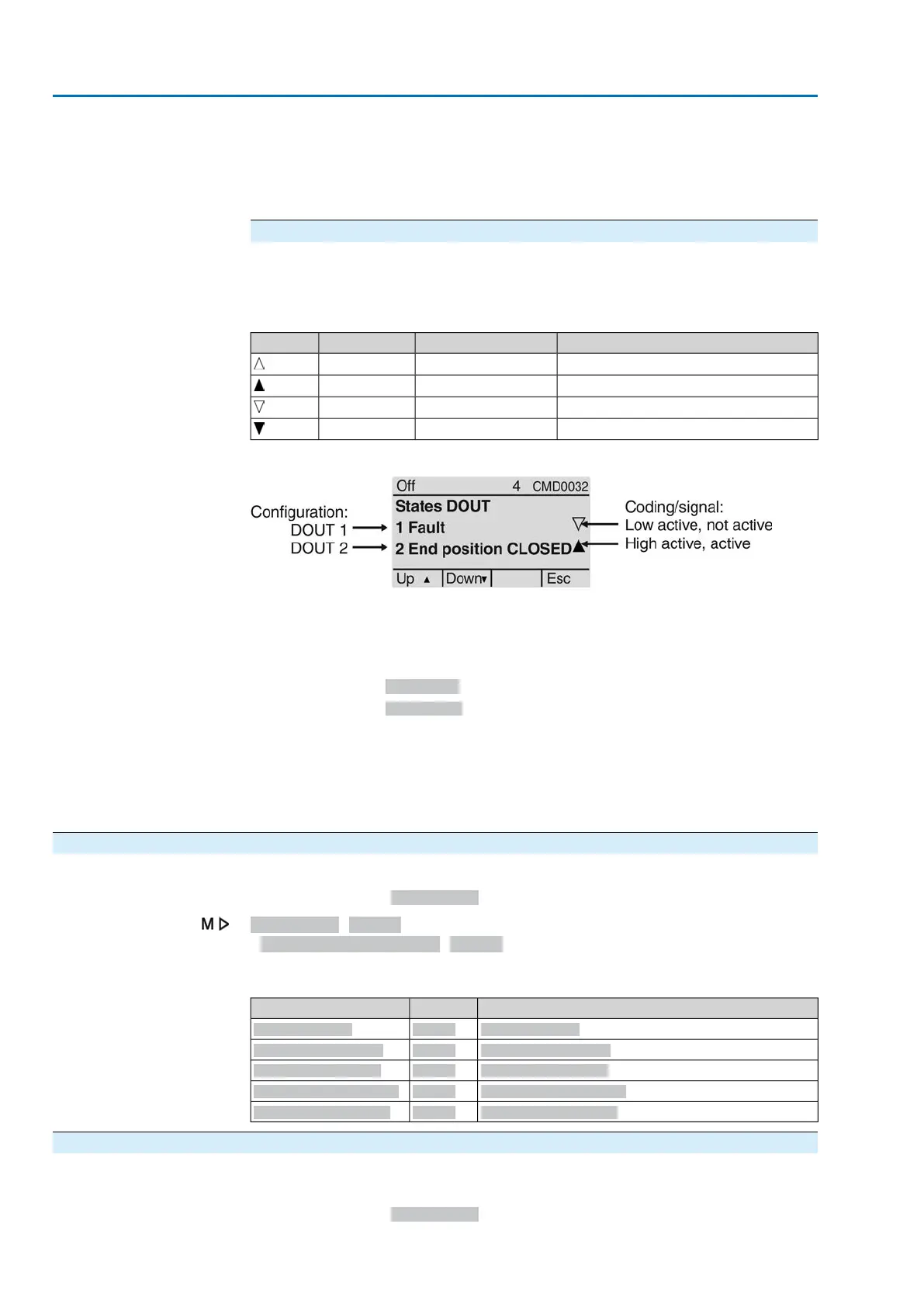
For the digital outputs (DOUT), both coding and signal states are indicated at the
output by means of symbols.
Table 20: Symbol explanation
State output (output contact)Signal (indication)CodeSymbol
Low = 0 (output contact not operated)Not activeHigh active
High = 1 (output contact operated)ActiveHigh active
High = 1 (output contact operated)Not activeLow active
Low = 0 (output contact not operated)ActiveLow active
Figure 58: Example of DOUT 1 and DOUT 2
●
Configuration:
- DOUT 1: Indication: Fault has occurred.
- DOUT 2: Indication: End position CLOSED reached
●
Coding:
-
DOUT 1: Low active (Triangle pointing in downward direction)
-
DOUT 2: High active (Triangle pointing in upward direction)
●
Signal state at output:
- DOUT 1: Not active (triangle not filled in)
High level = +24 V DC = no indication (no fault available)
- DOUT 2: Active (triangle is black)
High level = +24 V DC= indication (end position CLOSED reached)
14.4. Position transmitter and potentiometer diagnostic
Menu is only visible if the actuator is equipped with a potentiometer.
Required user level: Observer (1) or higher.
Diagnostics M0022
Position transm. potent. M0831
The following states can be checked via diagnostic:
SignificationMenu IDParameters
Low limit UspanM0832Low limit Uspan
Volt.level diff. potent.M0833Volt.level diff. potent.
Raw val. pos. OPENM0999Raw val. pos. OPEN
Raw val. pos. CLOSEDM1001Raw val. pos. CLOSED
Potent. raw value /mVM1005Potent. raw value /mV
14.5. Diagnostic Position transmitter RWG
Menu is only visible if the actuator is equipped with electronic position transmitter
(RWG).
Required user level: Observer (1) or higher.
130
Actuator controls
Diagnostics ACV 01.2/ACVExC 01.2 Profibus DP

 Loading...