Operating manual Ruby EN 16 | Electrical connection diagram
59
16 Electrical connection diagram
16.1 Electrical connection
NOTICE
Repairs to your pellet stove must only be carried out by authorised Austroflamm engineers.
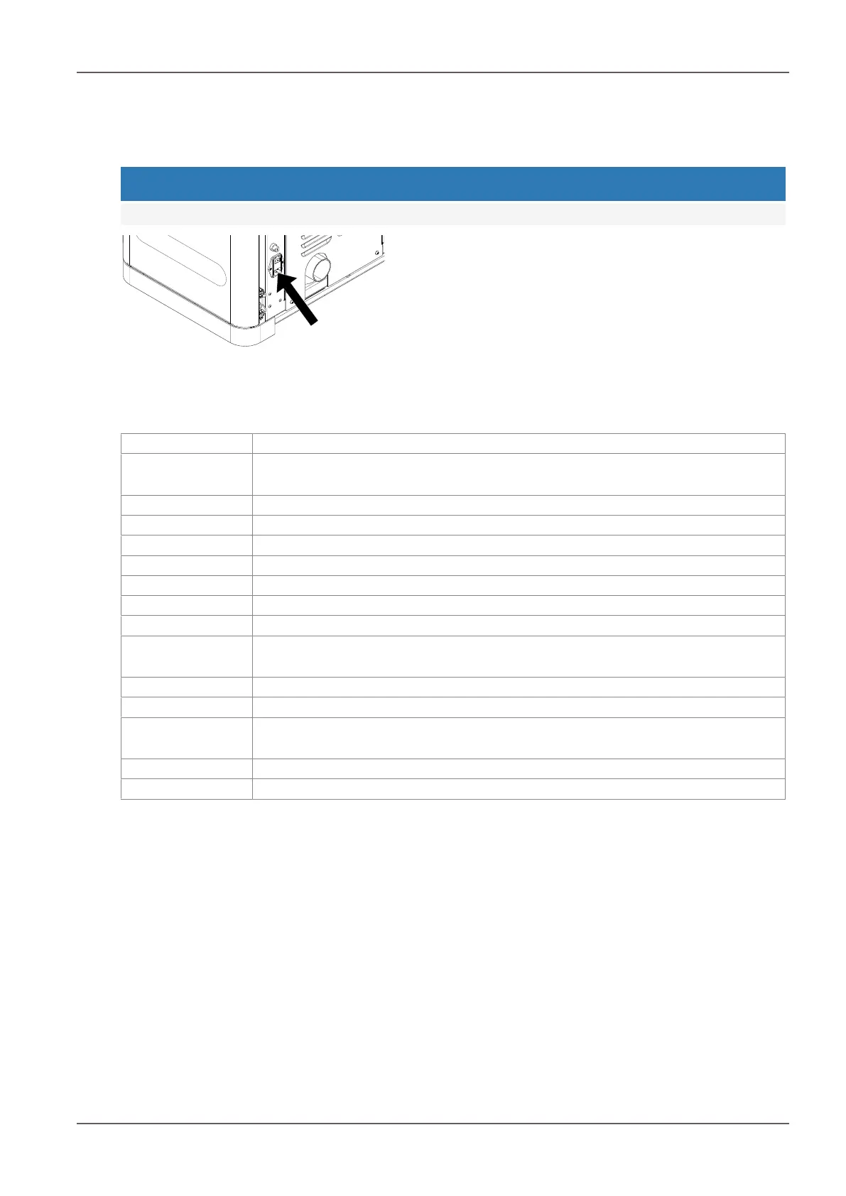
Fig.83: Fuse holder with T2.5A glass tube
fuses
Your pellet stove is designed for connection to a 230 V/50
Hz mains. The connection cable is included.
The mains socket connection is located on the rear of the
appliance and is protected with a T2.5 A glass tube fuse.
The power consumption of your pellet stove is visible on
the nameplate.
16.2 Model with permanently running screw motor
1. Phase converter
2. RPM / HAL-IC
Earth - induced-draft fan
3. Earth - DC control side
4. Room temperature sensor
5. Firebox temperature sensor
6. Differential pressure measurement P1, P2
7. Ceramic ignition
8. Induced-draught fan
9. Air distribution module (optional)
10. Control - permanently
running screw motor
11. Safety temperature limiter
12. Hopper lid switch
13. Grate motor, power release for
auger motor
14. Grate motor
(OPT) External thermostat