68 | P a g e
Technical Specification
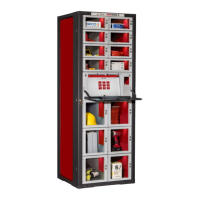
Frame: The Frame is external structure required to house & service Modules. The frame
provides a mounting hole pattern arrayed vertically in 3” increments, known as rack
spaces. FX frames are available in 6 ft. (24 rack space) and 3 ft. (12 rack space). System
control cables & DC power cables are housed in the right front vertical channel, and
upgrades for AC power and network are housed in the left channel.
CBI – CAN Bus Interface: The Controller Area Network protocol is a widely-used daisy-
chain bus topology network employed to connect and control low-power electrical &
electronic components. The FX main controller is known as the CAN Bus Interface (CBI)
board. A 5-wire cable with locking Hirose connectors is used to connect the CBI board to
the Distribution boards housed in the right channel of the frames. The CBI board
communicates with a local RoboCrib PC or FX Controller PC via Ethernet and is
configured as a Crib in the AutoCrib software. The CAN bus must be terminated at each
end, and both the CBI and the Distribution boards have termination headers available.
Proper termination is achieved by attaching a jumper shunt to the last header on each
end of the CAN bus.
I
2
C – “I-squared-C” – Bus: The sub-network employed to attach Latch boards to the
Distribution boards via 10-conductor ribbon cables or specialty mini-cables. Each Latch
board is independently addressable, and controls the latch it is attached to. It also
displays the LED status of the door or drawer it serves, and senses and reports the door
and latch status. The combined CAN bus and I2C architecture can serve up to 125 latch
boards. If additional latches are required in the array, another controller is added and
connected via Ethernet as a new Crib.
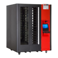
Touch Controller: This primary user interface is a special 12” deep drawer. It includes
the Dell PC, Touchscreen, bar code reader, CBI board, 12VDC power supply, one cooling
fan, a UPS, and 2 Ethernet adapters (one to the CBI, one spare). The power switch on
the UPS serves as the power cycling switch for the controller, like a current locker tower.
4 channel and out the top or bottom of the frame to connect to AC power (separate
from the frame power upgrade, which is reserved for the modules). The controller
drawer module is accompanied by folding tray, which is used for the keyboard. Drawer
has internal LED strips. The modules require 4 rack spaces (12”).
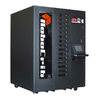
SuperRobo Controller sits on the top cover of the frame. It is a key-locked steel box with
grommeted holes for cable access, and its own strain-relieved power cord. It houses the