Automatic Systems Logic D1 v06-02-en0802.doc ERB-PM Technical manual
6/31
A. THE CONNECTORS
X1 (1:1) for the single-phase power supply:
PE: Earth. N: Neutral L: Live
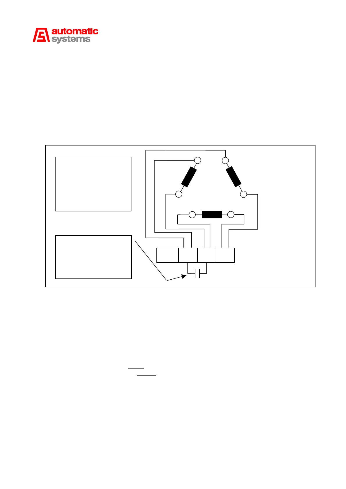
X2 (1:2) supplies the electrical power of the motor by U, V and W
(PE terminal have to be connected to the earth of the motor):
Important: it is necessary to install a starting capacitor between terminals U and V.
The following drawing shows how to connect a three-phase motor to the AS1200.
X3 (1:3) is used to plug in the board for sensors 1 and 2.
X4 (1:4) is used to plug in the board for sensors 3 and 4.
X5 (1:5) is used to connect an additional board (AS1220).
X6 (1:6) is used to connect another additional board (AS1210).
X7 (1:7) and X8 (1:8) are the two inputs (24V in negative logic with high impedance,
consumption of 10mA) and outputs connectors (relay: potential free contacts;
max. 48V, 100mA) making the following external connections possible:
U V WPE
Power Supply
230 V SINGLE-PHASE
240 V SINGLE-PHASE
110 V SINGLE-PHASE
TRIANGLE
W1
U2
V2
V1
W2 U1
Red
Green
Blue
Yellow
White
Black
CONNECTOR
X2 AS1200
Condenser :
BL 16 = 20µf
BL (other) = 40 µf
BL (other) 110V = 130 µf