Automatic Systems Logic D1 v06-02-en0802.doc ERB-PM Technical manual
7/31
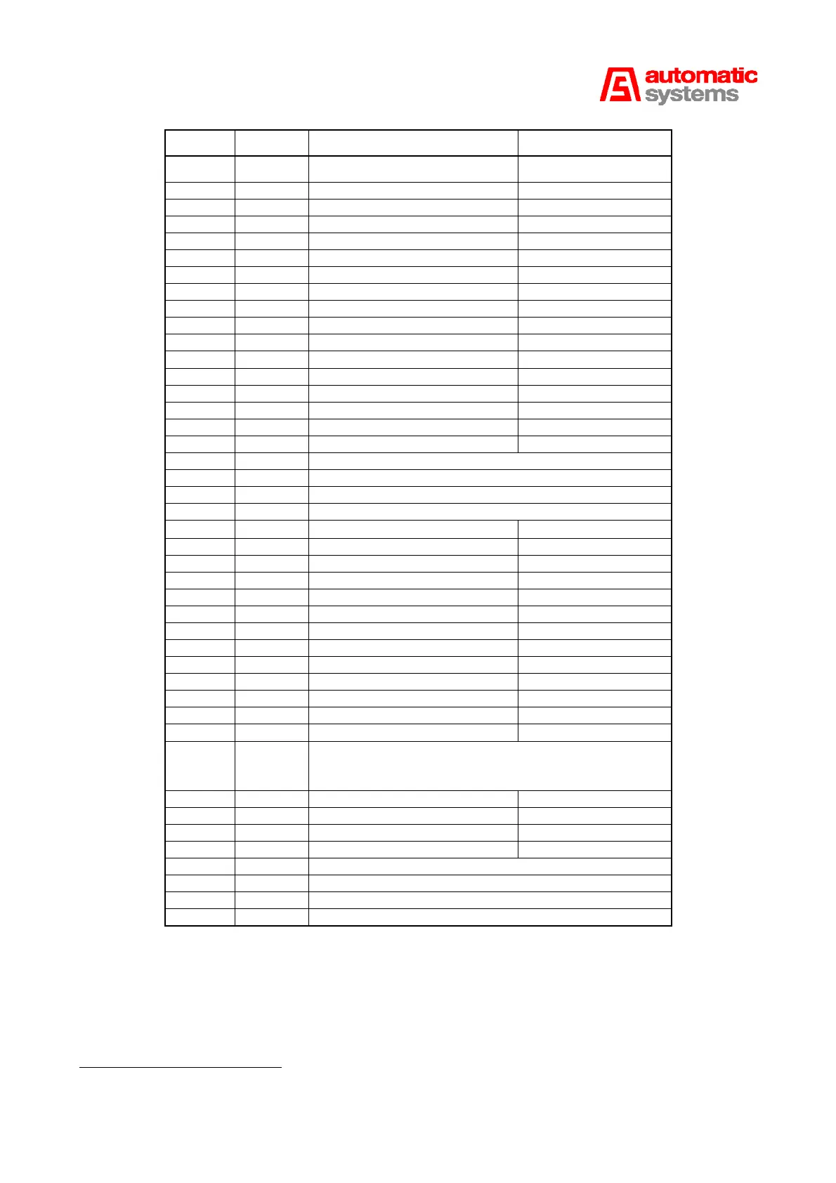
Position Terminal Function
X8 ↑
1 and 2 Output + 24V DC 150 mA Max.
3 Opening command 1 (OVB contact NO)
4 Ground
5 Closing command 1 (FRB contact NO)
6 Ground
7 Stop command 1 (NC contact)*
8 Stop command 1 (NC contact)*
9 Blocked open (NO contact)
10 Ground
11 Blocked closed (NO contact)
12 Ground
X7 ↑
13 Relay 1: Common
14 Relay 1: NC
15 Relay 1: NO
16 Relay 2: Common
17 Relay 2: NC
18 Relay 2: NO
19 Sensor 2 of the sensor board plugged on X3
20 Sensor 2 of the sensor board plugged on X3
21 Sensor 1 of the sensor board plugged on X3
22 Sensor 1 of the sensor board plugged on X3
X8 ↓
23 Opening command 2 (NO contact)
24 Ground
25 Opening command 3 (NO contact)
26 Ground
27 Closing command 2 (NO contact)
28 Ground
29 Closing command 3 (NO contact)
30 Ground
31 Stop command 2 (NC contact)*
32 Stop command 2 (NC contact)*
33 Stop command 3 (NC contact)*
34 Stop command 3 (NC contact)*
X7 ↓
35 Crank safety switch (FCM)
36 +24V DC (current comes out of the board and passes
through the crank switch: when the crank is introduced,
the contact opens and the motor is not longer powered)
37 Opening Limit Switch (FCO) (NC contact)
38 Ground (NC contact)
39 Closing Limit Switch (FCF) (NC contact)
40 Ground (NC contact)
41 Sensor 4 of the sensor board plugged on X4
42 Sensor 4 of the sensor board plugged on X4
43 Sensor 3 of the sensor board plugged on X4
44 Sensor 3 of the sensor board plugged on X4
X9 (1:9) is linked to the three-phase contactor command of the board AS1206 if this option is installed.
(In this case, the single-phase motor command relays
REL3 (1:22) and REL4 (1:23) are not plugged.)
X11 (1:10) is intended for the AS Link, to communicate with the console AS1033.
* These three STOP commands must be bridged if they are not connected or without SW4-DIP6.