Automatic Systems Logic D1 v06-02-en0802.doc ERB-PM Technical manual
9/31
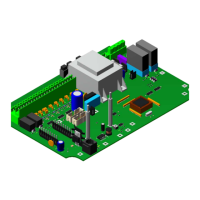
C. THE MICROCONTROLLER
IC1 (1:12) includes the complete program to control the barrier with all its options.
D. THE SWITCHES and the BUTTONS
SW2 (1:13): push button to activate the “Blocked-Open” command.
SW3 (1:14): push button to activate the “Blocked-Close” command.
(See paragraph 2.5.3. Hierarchy of the commands).
Note: To remain active the blocked commands, these buttons must be pushed in and maintained.
SW4 and its 8 DIP switches (1:15) allow to set the modes of operation and to program the different
parameters of the D1 unit.
SW5 (1:16) is the PGM button used to introduce the programming parameters when no console AS1033
is connected. The red LED LD2 (1:17) indicates the programming steps as well as some
function errors.
E. THE FUSES
F1 (1:18) is the 0.1A fuse for the power supply of the main board AS1200.
F2 (1:19) is the 3.15A protective fuse for the 220, 230 or 240 Volts single-phase motor.
is the 6.3A protective fuse for the 110, 120 or 130 Volts single-phase motor.
F. THE RELAYS
REL1 (1:20) and REL2 (1:21) may have various functions, such as communicate the status of the barrier
or activate the revolving light when the barrier is moving or managing a slave
barrier or one or two traffic lights with the board AS1049.
(see paragraph 2.4. Programming).
REL 3 (1:22) activates the motor to open the barrier in single-phase mode.
REL 4 (1:24) activates the motor to close the barrier in single-phase mode.
G. LIGHT EMITTING DIODES (LED)
LD 1 (1:24): green: watchdog
It flashes quickly when switched on and functioning normally.
In the event of the stopping of the processor, it will remain lit and the logic request to be
reset to zero.
LD 2 (1:17): red: visualisation of the programming stages or “HS” (out of order) indication.
indication of switch on for a few seconds.
LD 3 (1:25): green: indicates opening limit switch engaged.
LD 4 (1:25): green: indicates closing limit switch engaged.
LD 5 (1:25): green: indicates crank safety switch engaged.
LD 6 (1:25): green: indicates opening command.
LD 7 (1:25): green: indicates closing command.
LD 8 (1:25): green: indicates stop command.
LD 9 (1:25): green: indicates blocked-open command.
LD10 (1:25): green: indicates blocked-closed command.
LD11 (1:26): green: indicates the activation of relay REL1.
LD12 (1:26): green: indicates the activation of relay REL2.
LD15 (1:27): green: indicates activation of opening relay REL3.
LD16 (1:27): green: indicates activation of closing relay REL4.
LD17 (1:28): orange: presence of 24V DC.
LD18 (1:28): orange: presence of 5V DC.